Process image

Process image 1:

The six digital inputs of the module can be found under DIG Inputs 1 to 6.

  • Input 1 - socket 0, pin 4
  • Input 2 - socket 0, pin 2
  • Input 3 - socket 1, pin 4
  • Input 4 - socket 1, pin 2
  • Input 5 - socket 2, pin 4
  • Input 6 - socket 3, pin 4

Process image 2:

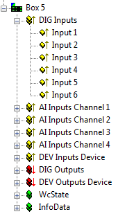
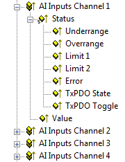
The four pressure measuring inputs of the module can be found under AI inputs Channel 1 to 4.

  • Underrange: the value fell below the underrange value
  • Overrange: the overrange value was exceeded
  • Limit1: the Limit1 value specified in the CoE objects was reached
  • Limit2: the Limit2 value specified in the CoE objects was reached
  • Error: one of the above events has occurred
  • Value: the pressure measured in the unit that was pre-scaled in the CoE objects (e.g. mbar).

Assignment of the channels to the connections at the housing

Process image 3:

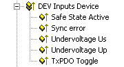
The diagnostic data for the module can be found under DEV Inputs Device.

  • Safe State Active: there was an interruption in communication, causing the outputs to change to the safe state
  • Sync error: a synchronization error has occurred
  • Undervoltage Us: the voltage US is less than approx. 18 VDC
  • Undervoltage Up: the voltage UP is less than approx. 18 VDC
  • TxPDO Toggle: EtherCAT variable for displaying a transmitted date of receipt (see general EtherCAT documentation)

Process image 4:

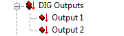
The two digital outputs of the module can be found under DIG Outputs 1 and 2.

  • Output 1 - socket 2, pin 2
  • Output 2 - socket 3, pin 2

Process image 5:

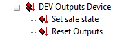
The output variables for setting or resetting the outputs of the module can be found under DEV Output Device.

  • Set safe state: the outputs change to the safe state (see CoE objects)
  • Reset Outputs: reserved

Process image 6:

These are standard EtherCAT variables; more information in the general EtherCAT manual.