Diag Messages
DiagMessages designates a system for the transmission of messages from the EtherCAT Slave to the EtherCAT Master/TwinCAT. The messages are stored by the device in its own CoE under 0x10F3 and can be read by the application or the System Manager. An error message referenced via a code is output for each event stored in the device (warning, error, status change).
Definition
The DiagMessages system is defined in the ETG (EtherCAT Technology Group) in the guideline ETG.1020, chapter 13 “Diagnosis handling”. It is used so that pre-defined or flexible diagnostic messages can be conveyed from the EtherCAT Slave to the Master. In accordance with the ETG, the process can therefore be implemented supplier-independently. Support is optional. The firmware can store up to 250 DiagMessages in its own CoE.
Each DiagMessage consists of
- Diag Code (4-byte)
- Flags (2-byte; info, warning or error)
- Text ID (2-byte; reference to explanatory text from the ESI/XML)
- Timestamp (8-byte, local slave time or 64-bit Distributed Clock time, if available)
- Dynamic parameters added by the firmware
The DiagMessages are explained in text form in the ESI/XML file belonging to the EtherCAT device: on the basis of the Text ID contained in the DiagMessage, the corresponding plain text message can be found in the languages contained in the ESI/XML. In the case of Beckhoff products these are usually German and English.
Via the entry NewMessagesAvailable the user receives information that new messages are available.
DiagMessages can be confirmed in the device: the last/latest unconfirmed message can be confirmed by the user.
In the CoE both the control entries and the history itself can be found in the CoE object 0x10F3:
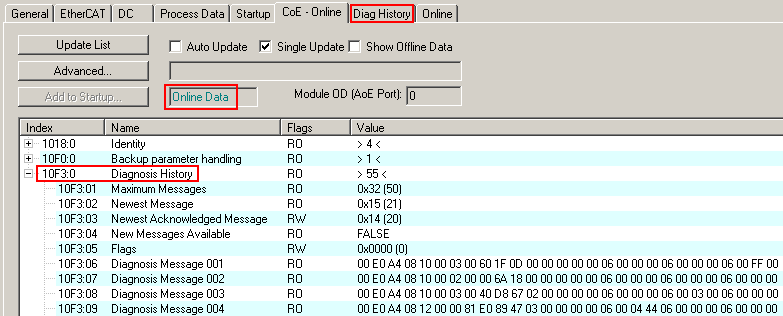
The subindex of the latest DiagMessage can be read under 0x10F3:02.
 | Support for commissioning The DiagMessages system is to be used above all during the commissioning of the plant. The diagnostic values e.g. in the StatusWord of the device (if available) are helpful for online diagnosis during the subsequent continuous operation. |
TwinCAT System Manager implementation
From TwinCAT 2.11 DiagMessages, if available, are displayed in the device’s own interface. Operation (collection, confirmation) also takes place via this interface.
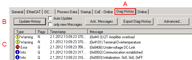
The operating buttons (B) and the history read out (C) can be seen on the Diag History tab (A). The components of the message:
- Info/Warning/Error
- Acknowledge flag (N = unconfirmed, Q = confirmed)
- Time stamp
- Text ID
- Plain text message according to ESI/XML data
The meanings of the buttons are self-explanatory.
DiagMessages within the ADS Logger/Eventlogger
From TwinCAT 3.1 build 4022 onwards, DiagMessages sent by the terminal are shown by the TwinCAT ADS Logger. Given that DiagMessages are represented IO- comprehensive at one place, commissioning will be simplified. In addition, the logger output could be stored into a data file – hence DiagMessages are available long-term for analysis.
DiagMessages are actually only available locally in CoE 0x10F3 in the terminal and can be read out manually if required, e.g. via the DiagHistory mentioned above.
In the latest developments, the EtherCAT Terminals are set by default to report the presence of a DiagMessage as emergency via EtherCAT; the event logger can then retrieve the DiagMessage. The function is activated in the terminal via 0x10F3:05, so such terminals have the following entry in the StartUp list by default:
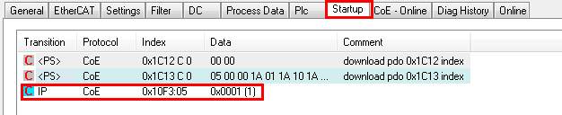
If the function is to be deactivated because, for example, many messages come in or the EventLogger is not used, the StartUp entry can be deleted or set to 0. The value can then be set back to 1 later from the PLC via CoE access if required.
Reading messages into the PLC
- In preparation -
Interpretation
Time stamp
The time stamp is obtained from the local clock of the terminal at the time of the event. The time is usually the distributed clock time (DC) from register x910.
Please note: When EtherCAT is started, the DC time in the reference clock is set to the same time as the local IPC/TwinCAT time. From this moment the DC time may differ from the IPC time, since the IPC time is not adjusted. Significant time differences may develop after several weeks of operation without a EtherCAT restart. As a remedy, external synchronization of the DC time can be used, or a manual correction calculation can be applied, as required: The current DC time can be determined via the EtherCAT master or from register x901 of the DC slave.
Structure of the Text ID
The structure of the MessageID is not subject to any standardization and can be supplier-specifically defined. In the case of Beckhoff EtherCAT devices (EL, EP) it usually reads according to xyzz:
x | y | zz |
|---|---|---|
0: Systeminfo | 0: System | Error number |
Example: Message 0x4413 --> Drive Warning Number 0x13
Text IDs of the ELM72xx
Text ID | Type | Location | Text Message | Comment |
|---|---|---|---|---|
0x1201 | Information | Communication | Communication re-established | Connection established |
0x4101 | Warning | General | Terminal-Overtemperature | Overtemperature. The internal temperature of the terminal exceeds the parameterized warning threshold. |
0x4102 | Warning | General | PDO-configuration is incompatible to the selected mode of operation | The selected PDOs do not match the set operation mode. Example: Drive operates in velocity mode. However, the velocity PDO is not mapped in the PDOs. |
0x4107 | Warning | General | Undervoltage Up |
|
0x4109 | Warning | General | Overvoltage Up |
|
0x410A | Warning | General | Fan |
|
0x410B | Warning | General | Error detected, but disabled by suppression mask |
|
0x4201 | Warning | Communication | No communication to field-side (Auxiliary voltage missing) |
|
0x4301 | Warning | Encoder | Feedback-Warning | General encoder error |
0x4411 | Warning | Drive | DC-Link undervoltage | The DC link voltage of the terminal is lower than the parameterized minimum voltage. Activation of the output stage is prevented. |
0x4412 | Warning | Drive | DC-Link overvoltage | The DC link voltage of the terminal is higher than the parameterized maximum voltage. Activation of the output stage is prevented. |
0x4413 | Warning | Drive | I2T Amplifier overload |
|
0x4414 | Warning | Drive | I2T Motor overload |
|
0x4415 | Warning | Drive | Speed limitation active | The maximum speed is limited by the parameterized objects (e.g. velocity limitation, motor speed limitation). This warning is output if the set velocity is higher than one of the parameterized limits. |
0x4417 | Warning | Drive | Motor-Overtemperature | The internal temperature of the motor exceeds the parameterized warning threshold. |
0x4418 | Warning | Drive | Limit: Current | Limit: Current is limited |
0x4419 | Warning | Drive | Limit: Amplifier I2T-model exceeds 100%% | The threshold values for the maximum current were exceeded. |
0x441A | Warning | Drive | Limit: Motor I2T-model exceeds 100%% | Limit: Motor I2T-model exceeds 100% |
0x441B | Warning | Drive | Limit: Velocity limitation | The threshold values for the maximum speed were exceeded. |
0x441C | Warning | Drive | Axis disabled via STO | An attempt was made to activate the axis, despite the fact that no voltage is present at the STO input. |
0x4420 | Warning | Drive | Cogging compensation not supported (%u) |
|
0x4421 | Warning | Drive | I2T-Model Brake chopper overload |
|
0x4422 | Warning | Drive | Limit: Brake chopper I2T-model exceeds 100%% |
|
0x4423 | Warning | Drive | Brake resistor not connected |
|
0x4424 | Warning | Drive | Modes of operation invalid |
|
0x8104 | Error | General | Terminal-Overtemperature | The internal temperature of the terminal exceeds the parameterized error threshold. Activation of the terminal is prevented. |
Text ID | Type | Location | Text Message | Comment |
|---|---|---|---|---|
0x8105 | Error | General | PD-Watchdog | Communication between the fieldbus and the output stage is secured by a watchdog. The axis is stopped automatically if the fieldbus communication is interrupted.
|
0x810A | Error | General | Fan |
|
0x810B | Error | General | Undervoltage Up |
|
0x810C | Error | General | Overvoltage Up |
|
0x8135 | Error | General | Cycletime has to be a multiple of 125 µs | The I/O or NC cycle time divided by 125 µs does not produce a whole number. |
0x8137 | Error | General | Electronic name plate: CRC error | Content of the external nameplate memory invalid. |
0x8144 | Error | General | Hardware fault (%d) |
|
0x817F | Error | General | Error: 0x%X, 0x%X, 0x%X |
|
0x81B0 | Error | General | Content of PDO 0x%X is invalid: Item 0x%X:%X cannot be mapped |
|
0x81B1 | Error | General | Content of PDO 0x%X is invalid: Item 0x%X:%X has an unsupported length (%d bit) |
|
0x8201 | Error | Communication | No communication to field-side (Auxiliary voltage missing) |
|
0x8302 | Error | Encoder | Feedback-Error | The amplitude of the resolver is too small. |
0x8304 | Error | Encoder | OCT communication error | Encoder communication error |
0x831A | Error | Encoder | Number of encoder-increments per revolution is not a power of two |
|
0x8403 | Error | Drive | ADC Error | Error during current measurement in the ADC |
0x8404 | Error | Drive | Overcurrent | Overcurrent in phase U, V or W |
0x8405 | Error | Drive | Modulo position invalid (feedback position has changed too much while drive was turned off) | Modulo position invalid |
0x8406 | Error | Drive | Undervoltage DC-Link | The DC link voltage of the terminal is lower than the parameterized minimum voltage. Activation of the output stage is prevented. |
0x8407 | Error | Drive | Overvoltage DC-Link | The DC link voltage of the terminal is higher than the parameterized maximum voltage. Activation of the output stage is prevented. |
0x8408 | Error | Drive | I2T-Model Amplifier overload |
|
0x8409 | Error | Drive | I2T-Model motor overload |
|
0x840B | Error | Drive | Commutation error |
|
0x840C | Error | Drive | Motor not connected |
|
0x8415 | Error | Drive | Invalid modulo range | Modulo factor invalid |
0x8416 | Error | Drive | Motor-Overtemperature | The internal temperature of the motor exceeds the parameterized error threshold. The motor stops immediately. Activation of the output stage is prevented. |
0x8417 | Error | Drive | Maximum rotating field velocity exceeded | Rotary field speed exceeds the value specified for dual use (EU 1382/2014). |
0x841C | Error | Drive | STO while the axis was enabled | An attempt was made to activate the axis, despite the fact that no voltage is present at the STO input. |
0x8420 | Error | Drive | Teach-In Process (%d) failed |
|
0x8421 | Error | Drive | Teach-In Process Timeout (STO, DC-Link, ...) |
|
0x8422 | Error | Drive | Drive configuration missing |
|
0x8423 | Error | Drive | Invalid process data format (number of singleturn bits+multiturn bits != 32) |
|
0x8441 | Error | Drive | Maximum following error distance exceeded |
|
0x8443 | Error | Drive | Invalid value for Mode of Operation |
|
0x8445 | Error | Drive | I2T-Model Brake chopper overload |
|
0x8446 | Error | Drive | Brake chopper overcurrent |
|
0x8448 | Error | Drive | Drive / axis is not referenced |
|
0x8449 | Error | Drive | Target position not in modulo range |
|
0x844A | Error | Drive | Modulo position: Checksum error |
|
0x844B | Error | Drive | Modulo position: Storage not supported for singleturn encoder |
|
0x844C | Error | Drive | Position offset cannot be used in the selected configuration |
|
0x8450 | Error | Drive | Invalid start type 0x%x |
|
0x8451 | Error | Drive | Invalid limit switch level |
|
0x8452 | Error | Drive | Drive error during positioning |
|
0x8453 | Error | Drive | Latch unit will be used by multiple modules |
|
0x8454 | Error | Drive | Drive not in control |
|
0x8455 | Error | Drive | Invalid value for "Target acceleration" |
|
0x8456 | Error | Drive | Invalid value for "Target deceleration" |
|
0x8457 | Error | Drive | Invalid value for "Target velocity" |
|
0x8458 | Error | Drive | Invalid value for "Target position" |
|
0x8459 | Error | Drive | Emergency stop active |
|
0x845A | Error | Drive | Target position exceeds Modulofactor |
|
0x845B | Error | Drive | Drive must be disabled |
|
0x845C | Error | Drive | No Feedback found |
|
0x845D | Error | Drive | Modulo factor invalid |
|
0x845E | Error | Drive | Invalid target position window |
|