Parameter
CoE parameters
The CoE parameters for configuring Drive Motion Control can be found in the following CoE objects:
- 0x8n20 "DMC Settings Ch.n"
- 0x8n21 "DMC Features Ch.n"
Scaling factor and maximum velocity
Position values are defined as 64-bit variables at Drive Motion Control.
The low-order 32 bits resolve the single-turn increments. The possibly lower resolution of the feedback is extrapolated to the full 32 bits.
The higher-order 32 bits represent the multi-turn revolutions.
The feed constant “Feed constant” includes any transmission ratios (gearbox, belt, etc.) and represents the output-side travel per motor revolution.
Therefore, the following exemplary formula without transmission ratio results for the scaling factor:

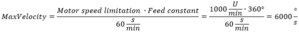
The maximum achievable velocity of the motor depends on the DC link voltage. If lower voltages than specified in the data sheet are used, the nominal speed may have to be adjusted to the voltage. To specify the maximum velocity of the motor in the CoE directory, the object 0x8n11:1B motor “Motor speed limitation” is also used. The DC link-dependent motor speed is specified here in 1/min. To adjust the speed of the scaling, this value is multiplied by the feed constant and normalized to the unit second. This results in the following formula for the exemplary calculation of the maximum speed:
The following sample shows the implementation in a PLC program:
PROGRAM MAIN
VAR
   DmcAxis:   AXIS_REF
END_VAR
// Update the axis structure
DmcAxis.ReadStatus();

// Scaling factor without gear ratio, feed constant 360°
DmcAxis.Parameter.EncoderScalingFactor := 0.000000083819031715393066;

// Velocity scaling with 1000 rpm, feed constant 360°
DmcAxis.Parameter.MaxVelocity := 6000;