Measurement SG 1/4 bridge (quarter-bridge) 2/3-wire connection
Notes
- Quarter-bridge measurement in 2-wire operation is not recommended in practice. The normal copper supply cables with their own resistance (e.g. ~17 mΩ/m with 1 mm² wire) and their very high temperature sensitivity (~4000 ppm/K, ~0.4%/K) have a considerable effect on the calculation and can only be corrected by continuous offset and gain adjustment. Only 3-wire operation should be used.
- Specifications apply to 5 V excitation.
The specification deteriorates at lower excitation voltage; Beckhoff does not have detailed information on this.
If a lower excitation voltage is desired for reasons of sensor self-heating, the excitation voltage can be temporarily switched on/off for non-continuous measurements (clocked operation). Switching on/off must be done from the controller via ADS access to the CoE 0x80n0:02. - Specifications apply to short cables, e.g. 5 m
In 3-wire mode, the lead resistances increase the resistance seen by the measuring device and thus reduce the measurable signal level; the noise component increases accordingly. The longer the supply cable, the more difficult it is to evaluate the signal; there is no theoretical maximum cable length. - Specifications only apply when using wire end sleeves and for cross-sections of 0.5 mm² or more. For smaller cross-sections, increased transition resistance is to be expected.
- Avoid repeated insertion/extraction of the push-in connectors in quarter-bridge operation, since this may increase the transition resistance.
- Integrated supply: 2...5V adjustable, max. supply/excitation 21 mA (internal electronic overload protection).
Note: effectively only half the voltage is present at the quarter-bridge due to the internally switched bridge supplement.
To calculate the quarter-bridge:
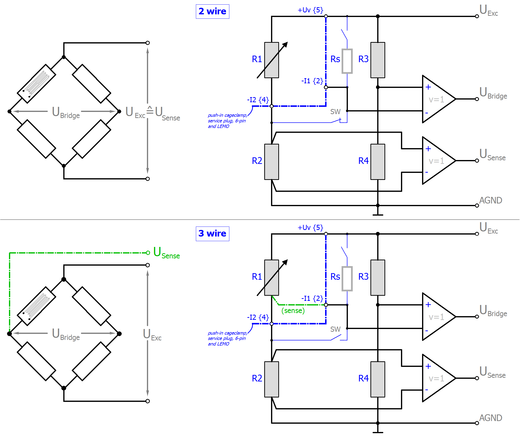 Fig.103: Connection of the quarter bridge
Explanation:
- R1: external quarter-bridge resistor, nominally 120/350/1000 Ω
- R2: internal supplementary resistor, is set to the same value as R1 after the CoE setting "Interface", and is therefore also 120, 350 or 1000 Ω
- R3, R4: high-resistance internal bridge supplementary resistors, therefore, do not significantly load the internal supply
- Rs: switchable shunt resistor
- SW: internal switch for 2/3-wire operation; open: 3-wire operation
The strain relationship (µStrain, µε) is as follows:
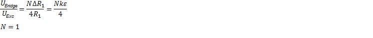
For the quarter-bridge, N=1 always applies.
The relationship between UBridge/UExc and ∆R1 is non-linear:
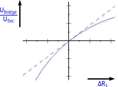 Fig.104: Relationship between UBridge/UExc and ∆R1
The ELM350x devices apply internal linearization so that the output is already linearized
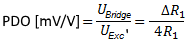
since the internal calculation is based on UExc'.
Measurement mode | StrainGauge/SG ¼-bridge 120 Ω 2/3-wire | |||
|---|---|---|---|---|
| 32 mV/V | 8 mV/V | 4 mV/V (comp.) 5) | 2 mV/V (comp.) 5) |
Measuring range, nominal | ±32 mV/V [corresponds to ±64,000 µε at K=2] 120 ± 15.36 Ω | ±8 mV/V [corresponds to ±16,000 µε at K=2] 120 ± 3.84 Ω | ±4 mV/V [corresponds to ±8,000 µε at K=2] 120 ± 1.92 Ω | ±2 mV/V [corresponds to ±4,000 µε at K=2] 120 ± 0.96 Ω |
Measuring range, end value (FSV) | 32 mV/V | 8 mV/V | 4 mV/V | 2 mV/V |
Measuring range, technically usable | ±34.359… mV/V | ±8.589… mV/V | ±4.294… mV/V | ±2.147… mV/V |
PDO resolution | 24 bit (including sign) | |||
PDO LSB (Extended Range) | 0.128 ppm | 0.128 ppm | 0.128 ppm | 0.128 ppm |
PDO LSB (Legacy Range) | 0.119… ppm | 0.119… ppm | 0.119… ppm | 0.119… ppm |
Specific data (cursive format = preliminary, not valid for ELM3704-1001)
Measurement mode | Measuring bridge/StrainGauge SG ¼-bridge 120 Ω 2/3-wire | ||||
|---|---|---|---|---|---|
| 32 mV/V | 8 mV/V | 4 mV/V (comp.) 5) | 2 mV/V (comp.) 5) | |
Basic accuracy: Measuring deviation at 23°C, with averaging, typ. 2) 6) | without Offset | < ±0.026 %FSV | < ±0.08 %FSV | < ±0.16 %FSV | < ±0.32 %FSV |
incl. Offset | < ±0.1 %FSV | < ±0.4 %FSV | < ±0.8 %FSV | < ±1.6 %FSV | |
Extended basic accuracy: Measuring deviation at 0…55°C, with averaging, typ. 2) 6) | without Offset | < ±0.164 %FSV | < ±0.565 %FSV | < ±1.1295 %FSV | < ±2.2585 %FSV |
incl. Offset | < ±0.1995 %FSV | < ±0.718 %FSV | < ±1.436 %FSV | < ±2.872 %FSV | |
Offset/Zero point deviation (at 23°C) 4) | EOffset | < 960 ppmFSV | < 3920 ppmFSV | < 7840 ppmFSV | < 15680 ppmFSV |
Gain/scale/amplification deviation (at 23°C) | EGain | < 160 ppm | < 520 ppm | < 1040 ppm | < 2080 ppm |
Non-linearity over the whole measuring range | ELin | < 200 ppmFSV | < 600 ppmFSV | < 1200 ppmFSV | < 2400 ppmFSV |
Repeatability, over 24 h, with averaging | ERep | < 25 ppmFSV | < 100 ppmFSV | < 200 ppmFSV | < 400 ppmFSV |
Noise (without filtering, at 23°C) | ENoise, PtP | < 310 ppm FSV | < 1200 ppm FSV | < 2400 ppm FSV | < 4800 ppm FSV |
ENoise, RMS | < 50 ppm FSV | < 200 ppm FSV | < 400 ppm FSV | < 800 ppm FSV | |
Max. SNR | > 86.0 dB | > 74.0 dB | > 68.0 dB | > tbd. dB | |
Noisedensity@1kHz | < 0.02 | < 0.02 | < 0.02 | < 0.02 | |
Noise (with 50/60 Hz FIR filter, at 23°C) 1) | ENoise, PtP | < 24 ppm FSV | < 72 ppm FSV | < 144 ppm FSV | < 288 ppm FSV |
ENoise, RMS | < 4.0 ppm FSV | < 12.0 ppm FSV | < 24.0 ppm FSV | < 48.0 ppm FSV | |
Max. SNR | > 108.0 dB | > 98.4 dB | > 92.4 dB | > 86.4 dB | |
Common-mode rejection ratio (without filter) 3) | tbd. | tbd. | tbd. | tbd. | |
Common-mode rejection ratio (with 50/60 Hz FIR filter) 1) 3) | tbd. | tbd. | tbd. | tbd. | |
Temperature coefficient, typ. | TcGain | < 20 ppm/K | < 48 ppm/K | < 96 ppm/K | < 192 ppm/K |
TcOffset | < 50 ppmFSV /K | < 180 ppmFSV /K | < 360 ppmFSV /K | < 720 ppmFSV /K | |
Largest short-term deviation during a specified electrical interference test | tbd. %FSV
| tbd. %FSV
| tbd. %FSV
| tbd. %FSV
| |
Input impedance ±Input 1 | Differential | tbd. | tbd. | tbd. | tbd. |
CommonMode | tbd. | tbd. | tbd. | tbd. | |
Input impedance ±Input 2 | 3-wire |
|
|
|
|
Differential | tbd. | tbd. | tbd. | tbd. | |
CommonMode | tbd. | tbd. | tbd. | tbd. | |

Measurement mode | StrainGauge/SG ¼-bridge 350 Ω 2/3-wire | |||
|---|---|---|---|---|
| 32 mV/V | 8 mV/V | 4 mV/V (comp.) 5) | 2 mV/V (comp.) 5) |
Measuring range, nominal | ±32 mV/V [corresponds to ±64,000 µε at K=2] 350 ± 44.8 Ω | ±8 mV/V [corresponds to ±16,000 µε at K=2] 350 ± 11.2 Ω | ±4 mV/V [corresponds to ±8,000 µε at K=2] 350 ± 5.6 Ω | ±2 mV/V [corresponds to ±4,000 µε at K=2] 350 ± 2.8 Ω |
Measuring range, end value (FSV) | 32 mV/V | 8 mV/V | 4 mV/V | 2 mV/V |
Measuring range, technically usable | ±34.359… mV/V | ±8.589… mV/V | ±4.294… mV/V | ±2.147… mV/V |
PDO resolution | 24 bit (including sign) | |||
PDO LSB (Extended Range) | 0.128 ppm | 0.128 ppm | 0.128 ppm | 0.128 ppm |
PDO LSB (Legacy Range) | 0.119… ppm | 0.119… ppm | 0.119… ppm | 0.119… ppm |
Specific data (cursive format = preliminary, not valid for ELM3704-1001)
Measurement mode | Measuring bridge/StrainGauge SG ¼-bridge 350 Ω 2/3-wire | ||||
|---|---|---|---|---|---|
| 32 mV/V | 8 mV/V | 4 mV/V (comp.) 5) | 2 mV/V (comp.) 5) | |
Basic accuracy: Measuring deviation at 23°C, with averaging, typ. 2) 6) | without Offset | < ±0.022 %FSV | < ±0.08 %FSV | < ±0.16 %FSV | < ±0.32 %FSV |
incl. Offset | < ±0.1 %FSV | < ±0.4 %FSV | < ±0.8 %FSV | < ±1.6 %FSV | |
Extended basic accuracy: Measuring deviation at 0…55°C, with averaging, typ. 2) 6) | without Offset | < ±0.0995 %FSV | < ±0.3715 %FSV | < ±0.7425 %FSV | < ±1.485 %FSV |
incl. Offset | < ±0.144 %FSV | < ±0.5565 %FSV | < ±1.113 %FSV | < ±2.2255 %FSV | |
Offset/Zero point deviation (at 23°C) 4) | EOffset | < 970 ppmFSV | < 3920 ppmFSV | < 7840 ppmFSV | < 15680 ppmFSV |
Gain/scale/amplification deviation (at 23°C) | EGain | < 120 ppm | < 440 ppm | < 880 ppm | < 1760 ppm |
Non-linearity over the whole measuring range | ELin | < 180 ppmFSV | < 650 ppmFSV | < 1300 ppmFSV | < 2600 ppmFSV |
Repeatability, over 24 h, with averaging | ERep | < 25 ppmFSV | < 100 ppmFSV | < 200 ppmFSV | < 400 ppmFSV |
Noise (without filtering, at 23°C) | ENoise, PtP | < 320 ppm FSV | < 1200 ppm FSV | < 2400 ppm FSV | < 4800 ppm FSV |
ENoise, RMS | < 55 ppm FSV | < 200 ppm FSV | < 400 ppm FSV | < 800 ppm FSV | |
Max. SNR | > 85.2 dB | > 74.0 dB | > 68.0 dB | > 61.9 dB | |
Noisedensity@1kHz | < 0.02 | < 0.02 | < 0.02 | < 0.02 | |
Noise (with 50/60 Hz FIR filter, at 23°C) 1) | ENoise, PtP | < 18 ppm FSV | < 72 ppm FSV | < 144 ppm FSV | < 288 ppm FSV |
ENoise, RMS | < 3.0 ppm FSV | < 12.0 ppm FSV | < 24.0 ppm FSV | < 48.0 ppm FSV | |
Max. SNR | > 110.5 dB | > 98.4 dB | > 92.4 dB | > 86.4 dB | |
Common-mode rejection ratio (without filter) 3) | tbd. | tbd. | tbd. | tbd. | |
Common-mode rejection ratio (with 50/60 Hz FIR filter) 1) 3) | tbd. | tbd. | tbd. | tbd. | |
Temperature coefficient, typ. | TcGain | < 12 ppm/K | < 50 ppm/K | < 100 ppm/K | < 200 ppm/K |
TcOffset | < 30 ppmFSV /K | < 110 ppmFSV /K | < 220 ppmFSV /K | < 440 ppmFSV /K | |
Largest short-term deviation during a specified electrical interference test | tbd. %FSV
| tbd. %FSV
| tbd. %FSV
| tbd. %FSV
| |
Input impedance ±Input 1 | Differential | tbd. | tbd. | tbd. | tbd. |
CommonMode | tbd. | tbd. | tbd. | tbd. | |
Input impedance ±Input 2 | 3-wire |
|
|
|
|
Differential | tbd. | tbd. | tbd. | tbd. | |
CommonMode | tbd. | tbd. | tbd. | tbd. | |
1) the 50/60 Hz filter setting must be selected via the settings in the CoE depending on the local mains frequency (50 or 60 Hz); the respective nominal mains frequency then applies as the measuring point for common mode rejection or crosstalk.
2) In real bridge measurement, an offset adjustment is usually carried out after installation. The given offset specification of the terminal is therefore practically irrelevant. Therefore, specification values with and without offset are given here. In practice, the offset component can be eliminated by the functions ELM Features and also ELM Features of the terminal or in the controller by a higher-level tare function. The offset deviation of a bridge measurement over time can change, therefore Beckhoff recommends a regular offset adjustment or careful observation of the change.
3) Values related to a common mode interference between SGND and internal ground.
4) The offset specification does not apply to 2-wire operation, since the offset is increased on the device side. Therefore, a system-side offset adjustment is recommended, see Tare- or ZeroOffset function. The final targeting basic acuuracy within the 2-wire operation is mainingly dependent by the quality of this system-side offset adjustment.
5) The channel measures electrically to 8 mV/V, but displays its measured value scaled to 2 or 4 mV/V. The Compensated function facilitates measurement of low levels even with high offset.
6) Calculated value according to the equation for estimating usability at the given ambient temperature point or estimating usability over the specified ambient temperature range in operation (Tambient) as stated in chapter "General information on measuring accuracy/measurement uncertainty". In real use, for example at a relatively constant ambient temperature Tambient, a lower (better) achievable uncertainty is attained. A specific calculation according to chapter "General information on measuring accuracy/measurement uncertainty" is recommended, especially if the instrument allows a wider ambient temperature range in operation than 0...55 °C.
Notice | |
Transition resistances of the connection contacts The transition resistance values of the connection contacts affect the measurement. The measuring accuracy can be further increased by a user-side adjustment with the signal connection plugged in. |
The temperature sensitivity of the terminal and thus of the measurement setup can be reduced if an external, more temperature-stable supplementary resistor is used for operation of the terminal in half-bridge or even full-bridge mode instead of the internal supplementary resistor for quarter-bridge mode.