Power supply, potential groups
The terminals from the ELM3xxx series have different structures depending on their function.
The electronics of a fieldbus-connected I/O device generally consists of two potential groups (exceptions possible, see respective device documentation):
- the communication section, the so-called bus side. This is usually supplied by the control voltage US.
In EtherCAT Terminals this section is directly connected to the internal 5 V supply from the E-bus and is not directly accessible by the user. - the signal section, for connecting the input/output signals, the so-called field side.
This is usually supplied by the peripheral voltage UP. It consists of 1..n function channels. - usually all channels of the device are contiguous in this island, there is no electrical isolation (separate GND) of the channels.
- in some devices, channels or channel groups may in turn be isolated as sub-islands. The height of the max. permissible electrical isolation is then specified. The device then consists of several potential groups: the bus side and the n channels.
- depending on the device, the field side can also be supplied
- indirectly via US by transporting the necessary power via the electrical isolation from the bus side to the field side; connection of UP (or power contacts) is then not required.
- directly via US - in special cases (e.g. EL6070 dongle terminal etc.) there is no accessible field side.
Both potential groups are usually electrically isolated. The "load capacity" of the isolation must then be observed in detail, i.e. the voltage difference/potential difference in continuous operation or for a short time between the two areas.
The internal electronics can be supplied via the bus side, field side or both, depending on the device. See the relevant notes about this in the respective device specification.
The plug used can also have an influence on the potential groups; if necessary, its housing is conductively connected to the housing of the terminal.
The external system GND (DIN rail, SGND, FE) is always present and represents the reference ground.
In the following the permissible potential difference is referred to only as "Insulation"; the exact specification (value, type and, if applicable, insulating strength) can be found in the respective specifications of the device.
Notice | |
Isolation between the potential groups in practice The potential groups are theoretically electrically isolated, i.e. there are only parasitic ohmic connections in the range of MΩ and higher that are unavoidable due to the electronics. |
The following potentials schematics may be specified for the ELM3xxx:
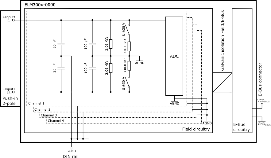 Fig.365: Potentials schematics ELM300x-0000
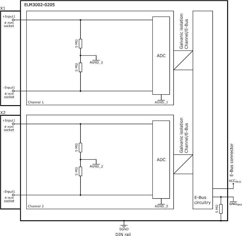 Fig.366: Potentials schematics ELM3002-0205
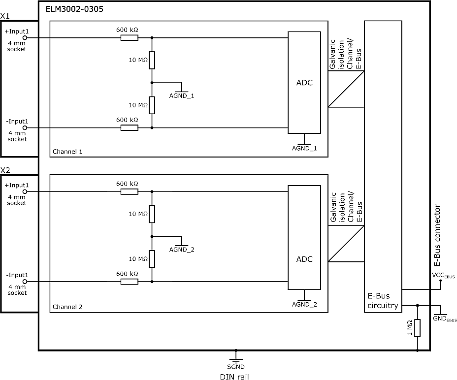 Fig.367: ELM3002-0305
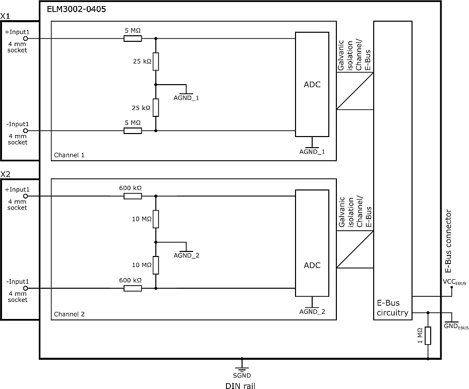 Fig.368: ELM3002-0405
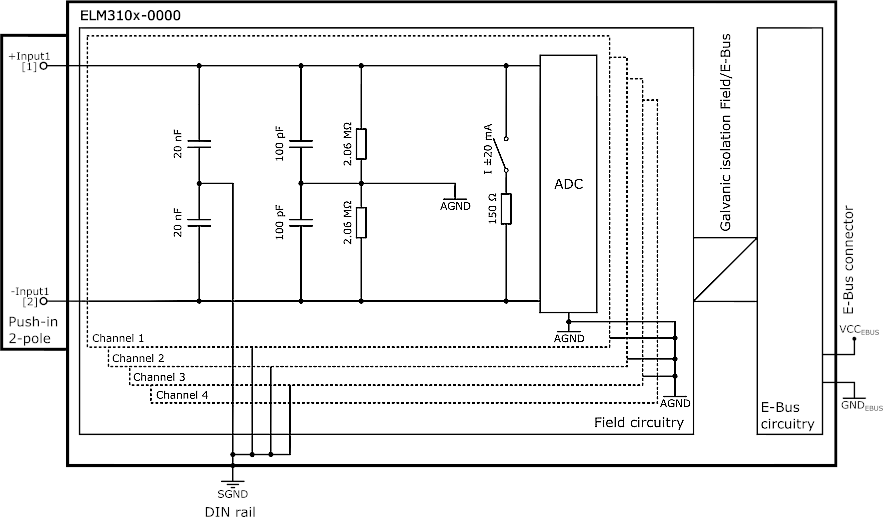 Fig.369: Potentials schematics ELM310x-0000
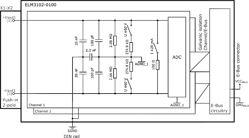 Fig.370: Potentials schematics ELM3102-0100
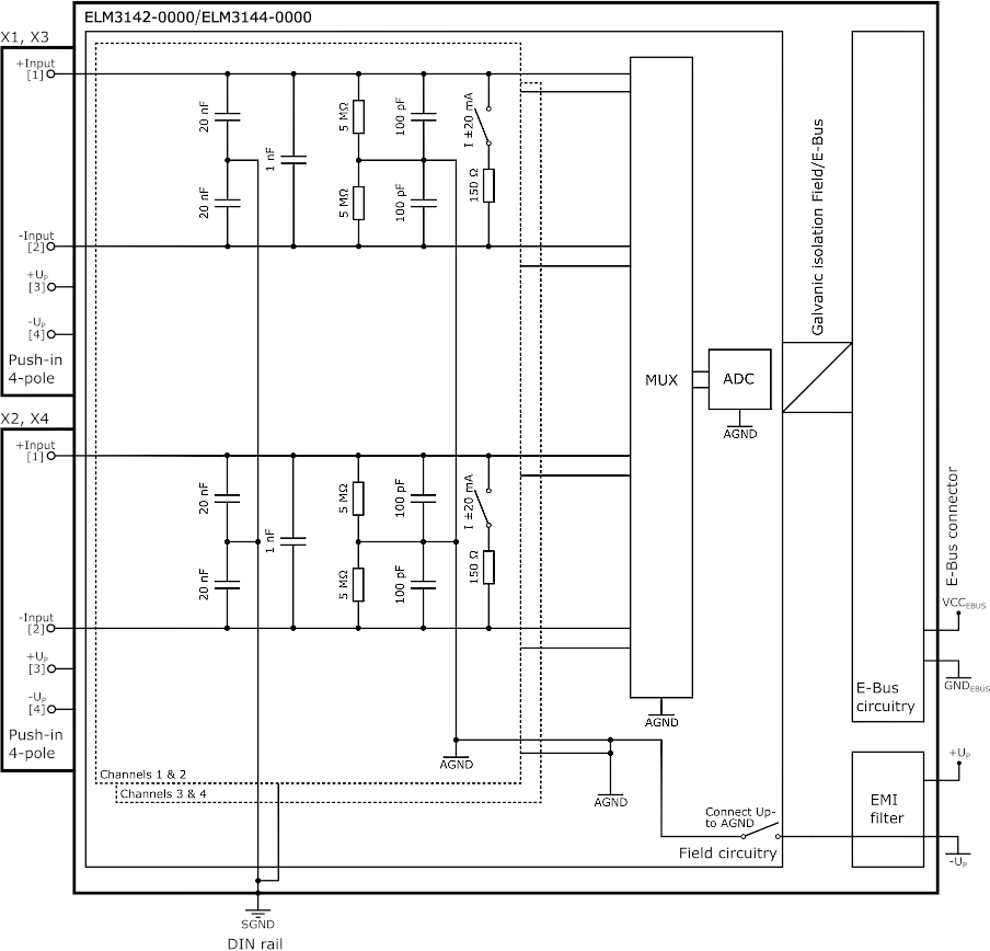 Fig.371: Potentials schematics ELM3142-0000/ ELM3144-0000
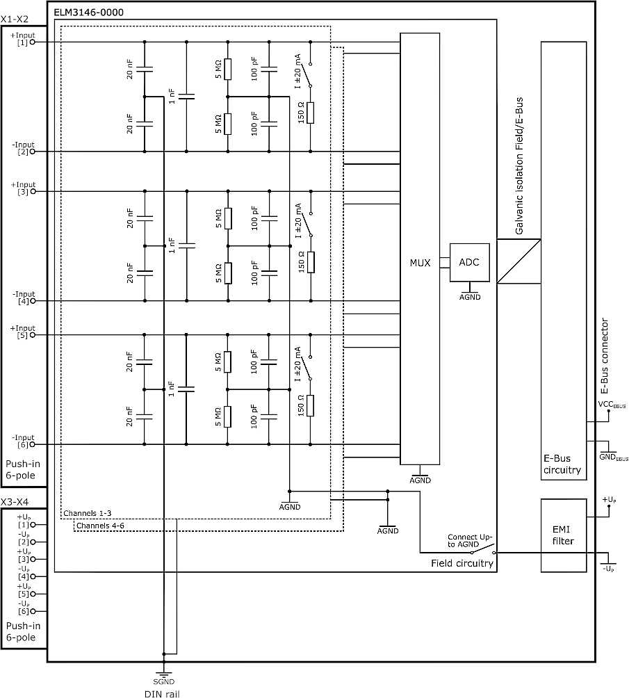 Fig.372: Potentials schematics ELM3146-0000
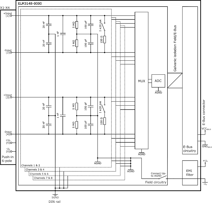 Fig.373: Potentials schematics ELM3148-0000
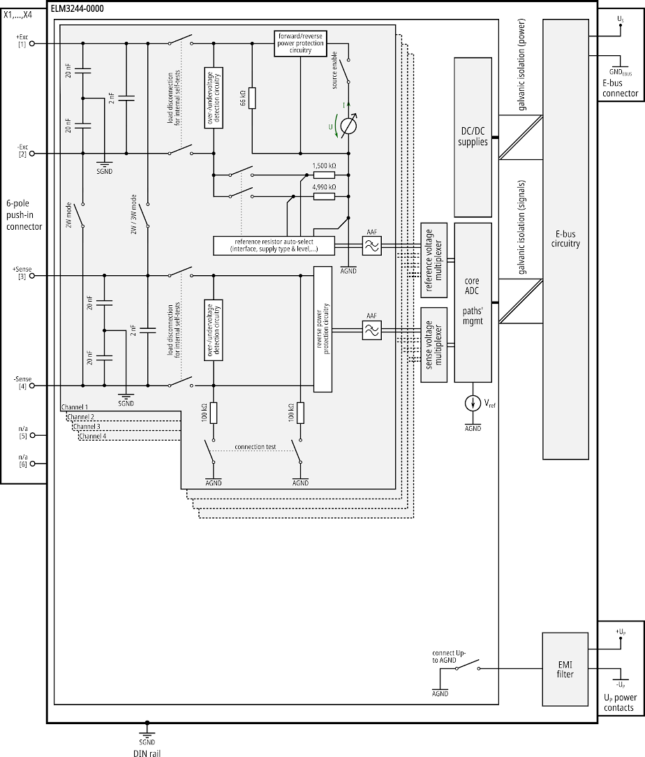 Fig.374: Potentials schematics ELM3244-0000
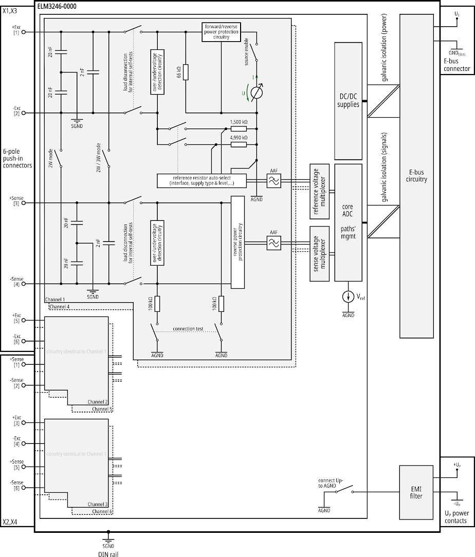 Fig.375: Potentials schematics ELM3246-0000
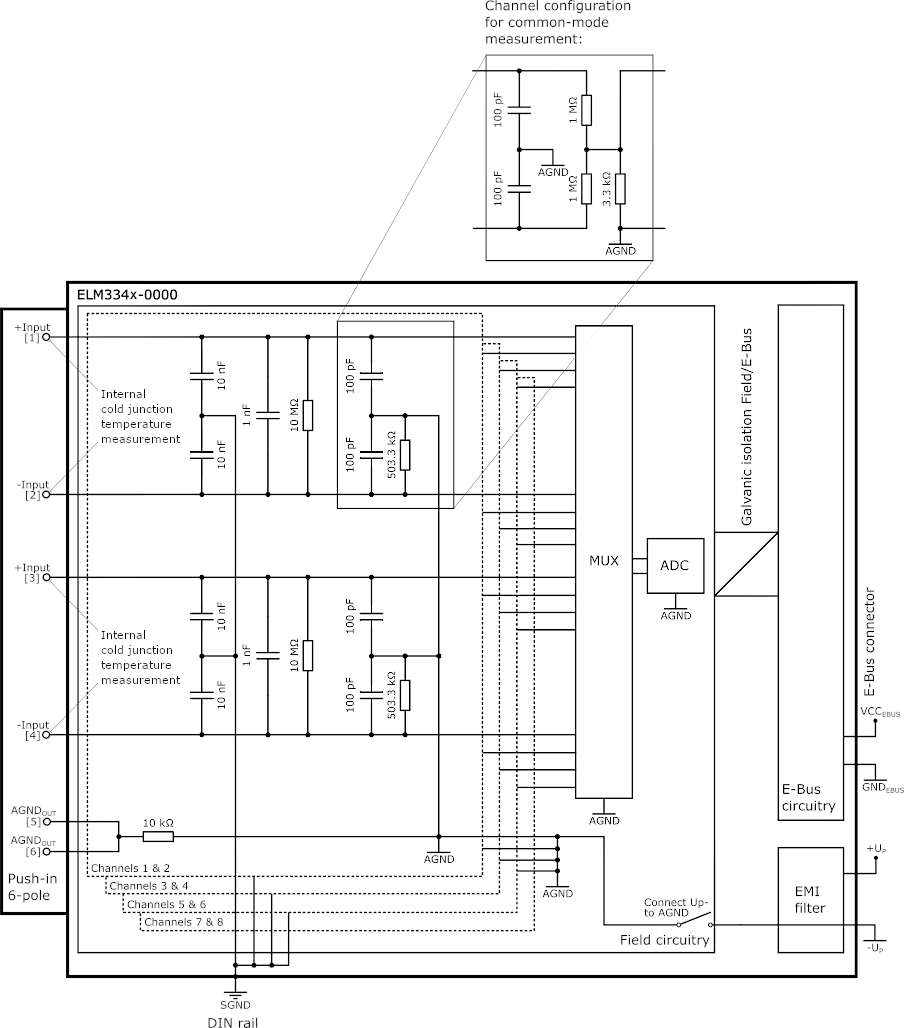 Fig.376: Potentials schematics ELM334x-0000
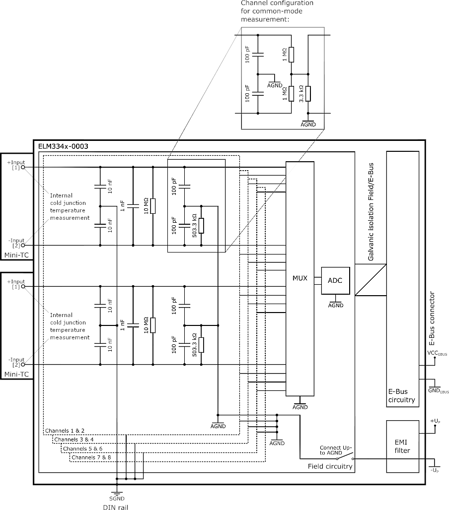 Fig.377: Potentials schematics ELM334x-0003
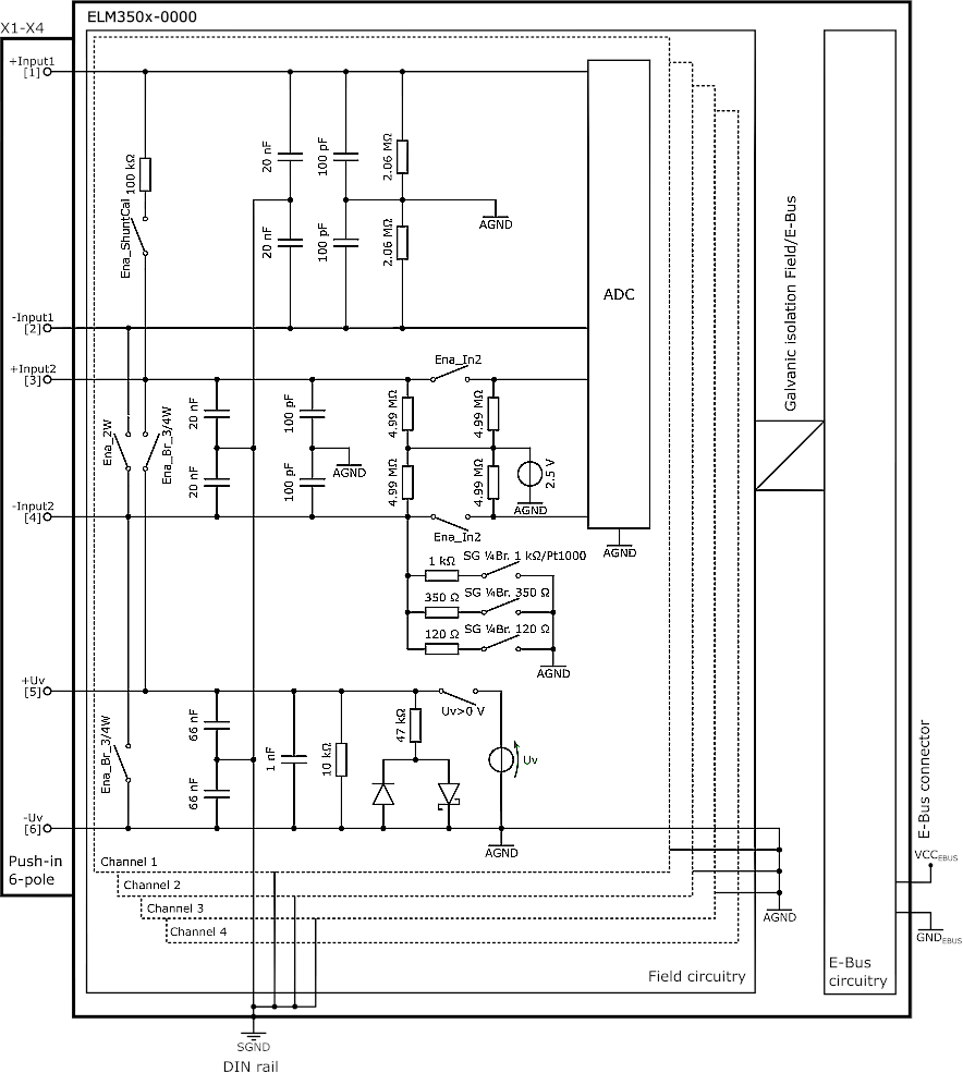 Fig.378: Potentials schematics ELM350x-0000
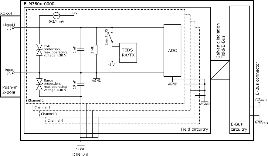 Fig.379: Potentials schematics ELM360x-0000
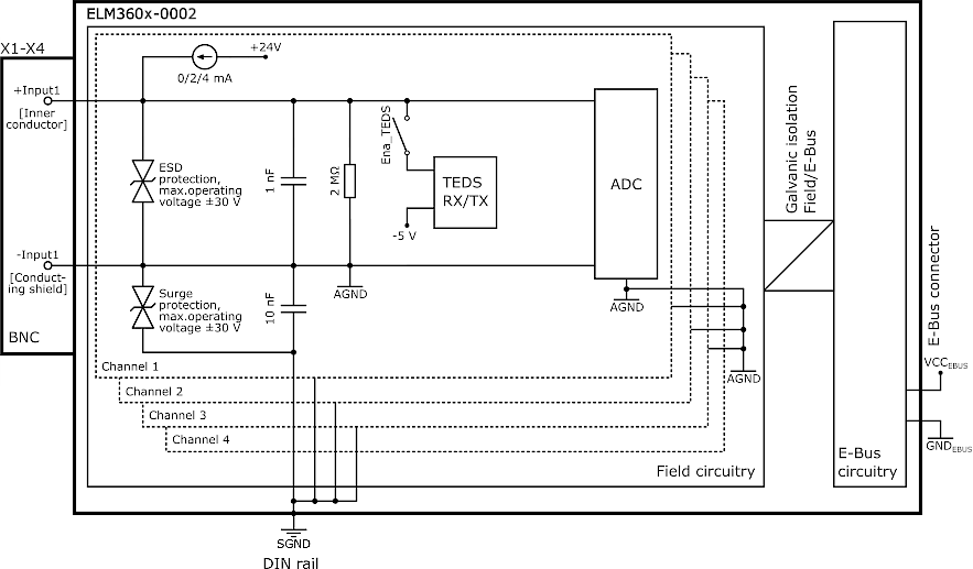 Fig.380: Potentials schematics ELM360x-0002
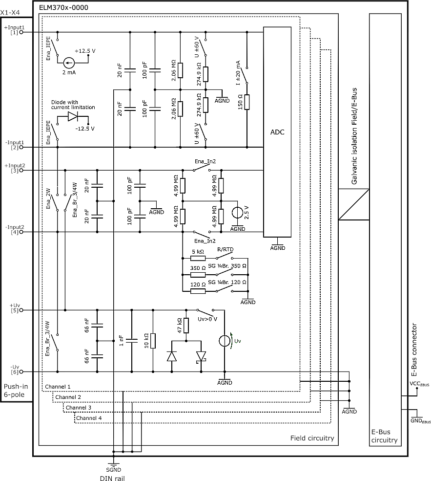 Fig.381: Potentials schematics ELM370x-0000
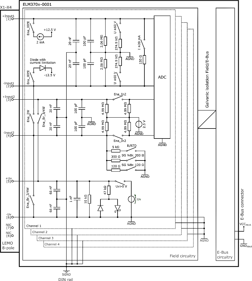 Fig.382: Potentials schematics ELM370x-0001
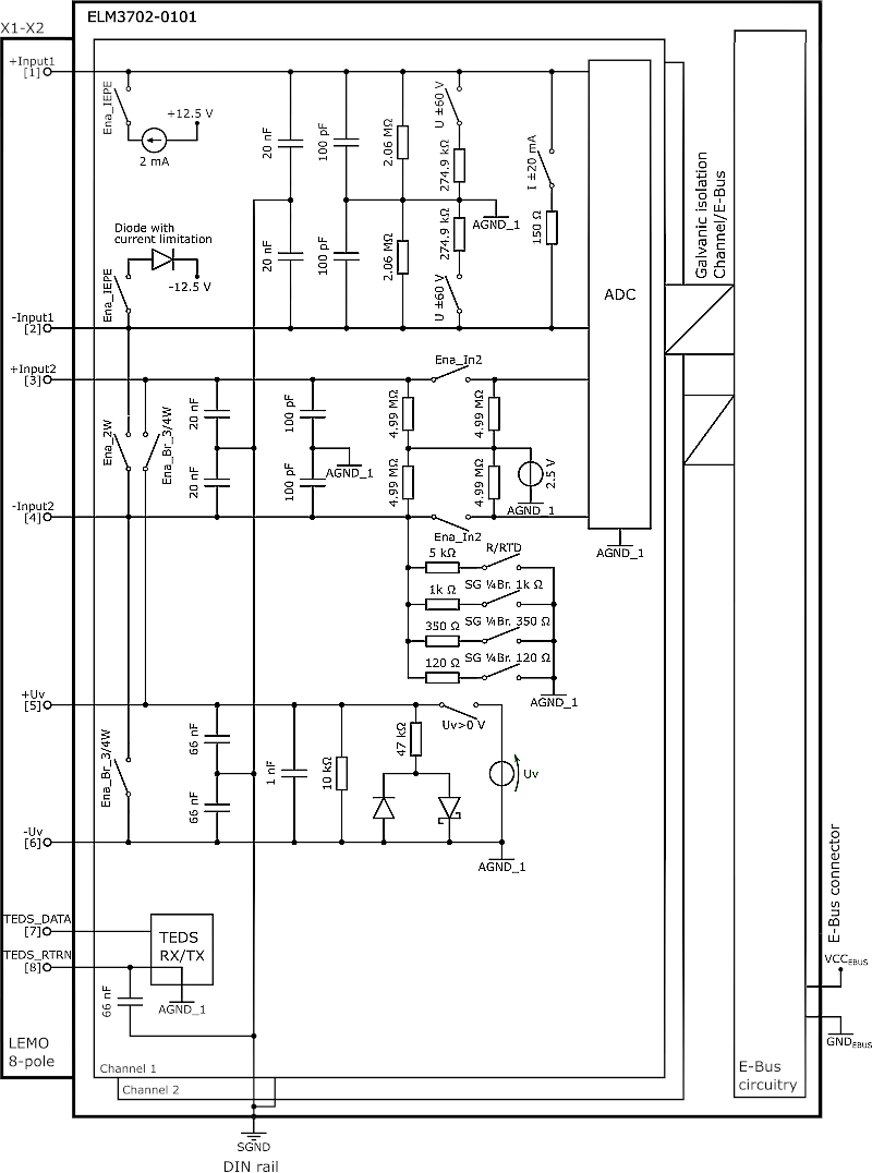 Fig.383: Potentials schematics ELM3702-0101
Schematics for further terminals in preparation.