Functional description
With EtherCAT switching output terminals with various switching technologies, digital or analog signals can be simply distributed through the opening and closing of electrical connection in a system-integrated manner. This method is sometimes used when several sensor signals are to be evaluated by a central analog input for reasons of cost or to simplify the circuit technology, i.e. a 1:n circuit. The n sensor lines are then fed to the central analog input one after the other in a defined rhythm, the so-called multiplex method. Below, an example is shown in which 16 vibration sensors are fed to two IEPE inputs:
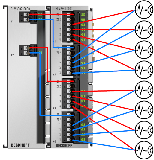 Fig.4: Multiplex example 16 to 2 channels with ELM2644 and ELM3602
The multiplex method can also be used on output potentials, i.e. an analog output can be distributed to several actuators in succession. In addition
- an n ⋅ m matrix structure can be realized by many switches,
- or lines can generally be temporarily disconnected, e.g. for diagnostic purposes and
- the principle can likewise be applied to digital signals (depending on the performance of the switches).
A recognizable disadvantage of this method is obvious and also determines the usage possibility: access to all sources is not continuously available. The application must allow a source to only be intermittently accessed. However, if a 1:1 connection of the signal sources with corresponding analog inputs is not necessary and the signals are given the necessary time to settle and stabilize after switching over, the multiplex method can often be the right solution in order to gain considerable space and cost advantages.
In relation to analog signals, the devices described in this documentation considerably extend the usage possibilities for standard and precision analog technology and enable:
- ATE: automated test equipment,
- HIL: hardware-in-the-loop systems,
- multi-channel temperature measurement in building material development,
- multi-channel vibration monitoring (Condition Monitoring),
- resistance simulation (by parallel connection).
Depending on
- the number of sources,
- the number of lines to be switched (six for 6-wire full bridge anyhow) and
- the number of analog inputs available,
the limit from when a multiplexer solution causes less costs and space requirements can be inferred. The higher the second number of lines to be switched, the more the switching effort increases and the later the use of a multiplexer is worthwhile – with a 2 or 3-wire circuit, the use of a multiplexer is already worthwhile very early on.
Hint: the series connection of multiplexers (multiplicative use)
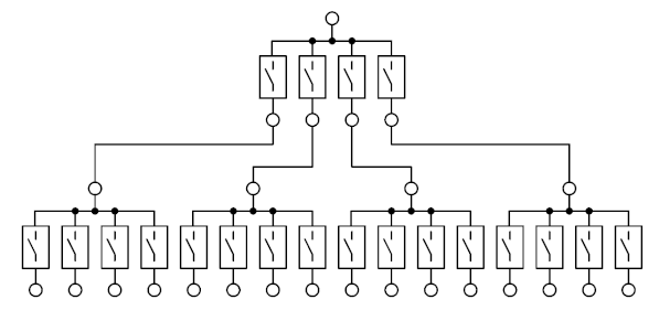 ,
,
requires more switches than the pure concatenation (additive use)
 ,
,
which is possible with the devices mentioned here, since the individual switches are NO (normally open, thus de-energized open).
Overview of the properties of the terminals in this documentation
The multiplex terminals
- are integrated directly into the EtherCAT fieldbus system as EtherCAT Terminals and can be controlled,
- contain reed switches (ELM264x, EL2642) or solid state relays (semiconductor, ELM274x) as high-quality switching elements, which have been specially selected for use on "small" sensitive analog signals.
The switching types have their individual advantages and disadvantages, see the recommendations for use.
Furthermore
- each switching element can be switched on/off individually like a digital output, independent of the others. It is therefore a single-pole single-throw (SPST) switch,
- the switches are not self-latching or bistable; they remain closed as long, and only as long as the corresponding output signal of the controller is applied via EtherCAT.
- Each switching element is NO/normally open, i.e. "opened" in the off state.
- The switches of a terminal are switched (over) internally at the same time, in DistributedClocks operation according to the DC Sync.; this makes simultaneous switching possible across terminals,
- Four switches are always grouped into a so-called 1:4 multiplexer group: the four input points are connected and led out to two contact points Z1.1 and Z1.2 on the terminal:
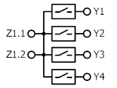 .
.
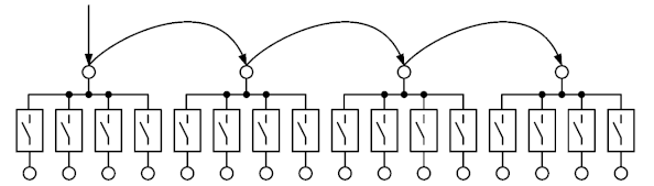
Due to the fact that the four switches are individually controllable (closable) and - if deactivated - all are open, this arrangement is strictly speaking not a pure multiplexer that always shows one (and only one) connection. Nevertheless, this term is widely used for the switching output terminals described here, as it best illustrates the typical use case. - One terminal contains several of these multiplexers. The X1 points can be connected externally, representing chained multiplexers. It is thus easy to form a 1:8 multiplexer, etc. from two 1:4 multiplexers:
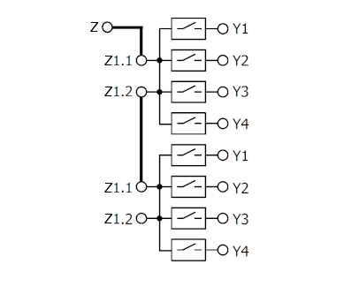 .
. - Matrix systems can also be set up with the terminals, the corresponding interconnection must be external:
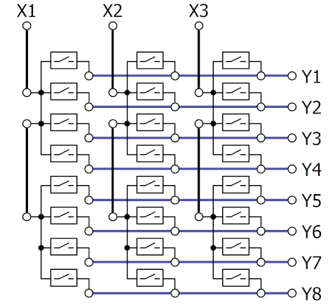 .
. - The naming scheme of the multiplex terminals is:
- EL/ELM26xx: EtherCAT Terminal Reed Relay,
- EL/ELM27xx: EtherCAT Terminal Solid State (semiconductor switches),
- EL/ELM2xab,
⋅ a: number of poles per multiplexer,
⋅ b: number of channels per terminal, corresponds to the number of multiplexers. - The terminals require the 24 V power contact supply for self-operation.
The multi-channel acquisition and ranking of analog signals, as well as the flexible switchover of various test states in production-integrated test stations, is easily possible through the integration of the often necessary changeover switches into the EtherCAT system.