EL9550-0010 - Connection, LEDs and process data
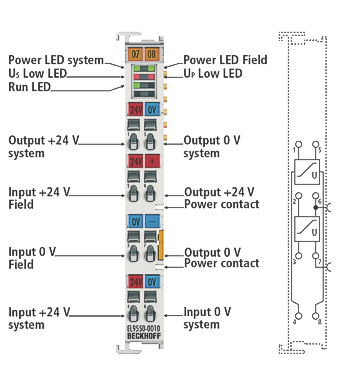 Fig.49: EL9550-0010
LED | Color | Meaning | |
|---|---|---|---|
Power-LED field | green | off | 24 VDC - field supply not available |
on | 24 VDC - field supply available | ||
Power-LED system | green | off | 24 VDC - system supply not available |
on | 24 VDC - system supply available | ||
Us Low LED | red | off | no error |
on | Undervoltage, Us below 18 V | ||
Up Low LED | red | off | no error |
on | Undervoltage, Up below 18 V | ||
RUN | green | These LEDs indicate the terminal's operating state: | |
off | State of the EtherCAT State Machine: INIT = initialization of the terminal | ||
Flashing | State of the EtherCAT State Machine: PREOP = function for mailbox communication and different default settings set | ||
Flashing | State of the EtherCAT State Machine: SAFEOP = verification of the Sync Manager channels and the distributed clocks. | ||
on | State of the EtherCAT State Machine: OP = normal operating state; mailbox and process data communication is possible | ||
Flashing | State of the EtherCAT State Machine: BOOTSTRAP = function for Firmware updates of the terminal, for example | ||
Terminal point | Description | |
|---|---|---|
Name | No. | |
Output +24 V system | 1 | Output +24 V (system) |
Input +24 V field | 2 | Input +24 V (field) |
Input 0 V field | 3 | Input 0 V (field) |
Input +24 V system | 4 | Input +24 V (system) |
Output 0 V system | 5 | Output 0 V (system) |
Input +24 V field | 6 | Input +24 V (field) (internally connected to positive power contact) |
Input 0 V field | 7 | Input 0 V (field) (internally connected to negative power contact) |
Input 0 V system | 8 | Input 0 V (system) |
Process data EL9550-0010
The EL9550-0010 has a bit width of 4 bits (diagnostic bits for Up/Us undervoltage and overvoltage) in the process image and is represented in the TwinCAT tree as follows:
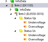 Fig.50: EL9550-0010 in the TwinCAT tree