EL9570 - Introduction and technical data Buffer capacitor terminal
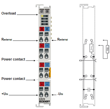 Fig.52: EL9570
The EL9570 EtherCAT Terminal contains high-performance capacitors for stabilizing supply voltages.
The EL9570 can be used, for example, in conjunction with the EL7041 stepper motor terminal, the EL7342 DC motor terminal or the EL7201 servomotor terminal.
Low internal resistance and high pulse current capability enable good buffering in parallel with a power supply unit. Reverse currents are stored, particularly in the context of drive applications, thereby preventing overvoltages. If the recovery energy exceeds the capacity of the capacitors, energy can be dissipated via an external braking resistor.
Technical data
Technical data | EL9570 |
|---|---|
Technology | Buffer capacitor |
Nominal voltage | 50 V |
Capacitance | 500 µF |
Ripple current | 10 A in continuous operation |
Internal resistance | < 10 mΩ |
Overvoltage protection | > 56 V |
Recommended braking resistor | 10 Ω, 10 W typ. |
Overvoltage control range | ±2 V |
Braking resistor clock rate | load-dependent, 2-point control |
Electrical isolation | 1500 V |
Diagnostics | - |
Message to E-bus | - |
Shield connection | - |
E-bus current consumption | - |
Bit width in process image | 0 |
Electrical connection to mounting rail | - |
Renewed infeed | - |
Connection facility to additional power contact | - |
Side by side mounting on EtherCAT Terminals with power contact | yes, left side without power contact ground |
Side by side mounting on EtherCAT Terminals without power contact | yes |
Dimensions (W x H x D) | approx. 15 mm x 100 mm x 70 mm (width aligned: 12 mm) |
Configuration | no address or configuration settings required |
Weight | approx. 90 g |
Permissible ambient temperature range during operation | 0 °C ... +55 °C |
Permissible ambient temperature range during storage | -25 °C ... +85 °C |
Permissible relative air humidity | 95 %, no condensation |
on 35 mm mounting rail, conforms to EN 60715 | |
Vibration / shock resistance | conforms to EN 60068-2-6 / EN 60068-2-27 |
EMC immunity / emission | conforms to EN 61000-6-2 / EN 61000-6-4 |
Protection rating | IP20 |
Installation position | variable, see chapter Mounting of passive terminals |
Approvals/markings*) |
*) Real applicable approvals/markings see type plate on the side (product marking).
Ex markings
Standard | Marking |
|---|---|
ATEX | II 3 G Ex ec IIC T4 Gc |
IECEx | Ex ec IIC T4 Gc |
Connection and LEDs EL9570
EL9570 – Connection and LEDs
Terminal point | Description | |
|---|---|---|
Name | No. | |
Rexternal | 1 | Connection for braking resistor |
+UIN | 2 | Positive input for buffer voltage (internally connected to terminal points 3 and 4) |
+UIN | 3 | Positive input for buffer voltage (internally connected to terminal points 2 and 4) |
+UIN | 4 | Positive input for buffer voltage (internally connected to terminal points 2 and 3) |
Rexternal | 5 | Connection for braking resistor |
-UIN | 6 | Negative input for buffer voltage (internally connected to terminal points 7 and 8) |
-UIN | 7 | Negative input for buffer voltage (internally connected to terminal points 6 and 8) |
-UIN | 8 | Negative input for buffer voltage (internally connected to terminal points 6 and 7) |
LED | Color | Meaning | |
|---|---|---|---|
Overload | green | off | No error |
on | Overload, energy is dissipated into external braking resistors | ||