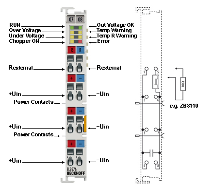
EL9576 - LEDs and pin assignment
 | Correct supply voltage is necessary for operation! In addition to the supply voltage via the contacts on the front panel, the voltage from the E-bus must also be present in order for the terminal to work properly, since the integrated logic of the Bus Terminal is supplied with this voltage. The Bus Terminal does not work if the supply is incorrect. |
Notice | |
Match the resistor power to the expected power! When selecting the external resistor, make sure that the rated power of the resistor is matched to the expected power, since otherwise the resistor and adjacent components can be damaged. In addition, the temperature model is to be adapted to this resistor. |
EL9576 - pin assignment
|
Terminal point |
Description | |
|---|---|---|
|
Name |
No. | |
|
R 50 V (Rexternal) |
1 |
+ connection of external resistor |
|
50 V (+Uin) |
2 |
+ supply voltage connection |
|
50 V (+Uin) |
3 |
+ supply voltage connection |
|
50 V (+Uin) |
4 |
+ supply voltage connection |
|
R GND (Rexternal) |
5 |
- connection of external resistor |
|
GND (-Uin) |
6 |
- supply voltage connection |
|
GND (-Uin) |
7 |
- supply voltage connection |
|
GND (-Uin) |
8 |
- supply voltage connection |
EL9576 - LEDs
|
LED |
Color |
Meaning | |
|---|---|---|---|
|
RUN |
green |
This LED indicates the terminal's operating state: | |
|
off |
State of the EtherCAT State Machine: INIT = initialization of the terminal | ||
|
flashing |
State of the EtherCAT State Machine: PREOP = function for mailbox communication and different standard-settings set | ||
|
single flash |
State of the EtherCAT State Machine: SAFEOP = verification of the Sync Manager channels and the distributed clocks. | ||
|
on |
State of the EtherCAT State Machine: OP = normal operating state; mailbox and process data communication is possible | ||
|
flickering |
State of the EtherCAT State Machine: BOOTSTRAP = function for firmware updates of the terminal | ||
|
Out voltage OK |
green |
ON |
Supply voltages are OK, there are no errors |
|
OFF |
| ||
|
Over voltage |
yellow |
ON |
The supply voltage has exceeded the threshold value for overvoltage. |
|
Temp warning |
yellow |
ON |
Temperature threshold value for the temperature on the PCB has been exceeded. |
|
Under voltage |
yellow |
ON |
The supply voltage is too low, or has fallen below the corresponding threshold value in the CoE data. |
|
Temp R warning |
yellow |
ON |
The “I2T warning level” threshold value has been exceeded. |
|
Chopper On |
yellow |
ON |
The external resistor is switched on. |
|
Error |
red |
ON + “Undervoltage” LED |
The supply voltage is not connected or is so low that the “supply voltage” and “ResistorCurrent” values cannot be read. |
|
ON + “Temp R Warning” LED + “Overvoltage” LED |
There is an overtemperature in the internal temperature simulation for the external resistor. | ||