EL9222-xxxx
LEDs and connection
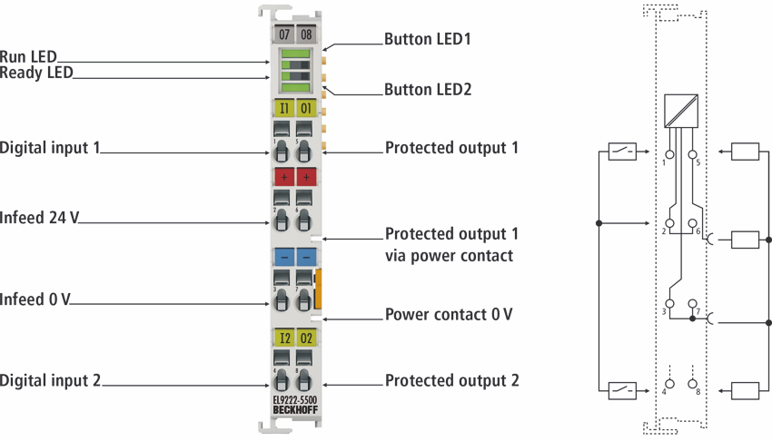
Meaning of the connections
Terminal point | Description | |
|---|---|---|
Name | No. | |
Digital input 1 | 1 | Digital input for switching output 1 |
24 V power supply | 2 | +24 V DC input voltage (internally connected to terminal point 6) |
0 V power supply | 3 | 0 V DC input voltage (internally connected to terminal point 7 and power contact 0 V) |
Digital input 2 | 4 | Digital input for switching output 2 |
Protected output 1 | 5 | Protected + 24 V DC (internally connected to positive power contact) |
Protected output 1 via power contact |
| Protected + 24 V DC (internally connected to output 1) |
24 V power supply | 6 | +24 V DC input voltage (internally connected to terminal point 2) |
0 V power supply | 7 | 0 V DC input voltage (internally connected to terminal point 3 and power contact 0 V) |
Protected output 2 | 8 | Protected + 24 V DC, |
Meaning of the EL9222-xxxx LEDs and button LEDs
LED | Color | Meaning | |
|---|---|---|---|
Button LED 1 | Button LED 1 indicates the status of output 1. | ||
Green
| off | Output 1 switched off | |
on | Output 1 switched on | ||
flashing | Programming mode active: | ||
flickering | Switch-off process not yet completed, | ||
Orange
| on | Output 1 switched on + prewarning threshold reached | |
Flash (after pressing) | Output 1 disabled (nominal current value is set to "OFF") | ||
flashing | Reverse current active | ||
Red
| on | Output 1 triggered | |
flashing | Output 1 triggered and cooling phase active | ||
Run LED | Run LED indicates the EtherCAT operating state of the terminal | ||
Green
| off | State of the EtherCAT State Machine: INIT = initialization of the terminal | |
flashing | State of the EtherCAT State Machine: PREOP = function for mailbox communication and different default settings set | ||
Single flash | State of the EtherCAT State Machine: SAFEOP = verification of the Sync Manager channels and the distributed clocks. | ||
on | State of the EtherCAT State Machine: OP = normal operating state; mailbox and process data communication is possible | ||
flickering | State of the EtherCAT State Machine: BOOTSTRAP = function for terminal firmware updates | ||
Ready LED | Ready LED indicates the status for overcurrent protection / programming mode / query mode | ||
Green | on | 24 V DC supply voltage present and initialization completed, overcurrent protection active, operation mode active | |
Orange | on | Programming mode / query mode active | |
Red | on | Missing 24 V DC supply voltage or initialization error | |
flashing | Loading the factory settings | ||
flickering | Wiring error or cable break (e.g. wrong ground reference) | ||
Button LED 2 | Button LED 2 indicates the status of output 2. | ||
Green
| off | Output 2 switched off | |
on | Output 2 switched on | ||
flashing | Programming mode active: | ||
flickering | Switch-off process not yet completed, | ||
Orange
| on | Output 2 switched on + prewarning threshold reached | |
Flash (after pressing) | Output 2 disabled (nominal current value is set to "OFF") | ||
flashing | Reverse current active | ||
Red
| on | Output 2 triggered | |
flashing | Output 2 triggered and cooling phase active | ||
 | The EL9222-xxxx has illuminated push-buttons! The illuminated push-buttons allow the overcurrent protection terminal to be operated, e.g. switching on and off and resetting the respective output. They are also used for programming and querying the nominal current. There are 3 modes: operation mode, programming mode and query mode. There is a common programming mode in which the two outputs can be set simultaneously, as they are interdependent for the terminal with sum current limitation. |
Overview of the 3 operation modes:
Operation mode
The operation mode is active as soon as the overcurrent protection terminal is supplied with supply voltage, the initialization has been successfully completed and no other mode is active. This is effectively the normal mode of operation.
Programming mode
The programming mode is available for the adjustable overcurrent protection terminals. To enter this mode, press and hold one of the two buttons in operation mode for > 3 seconds. In programming mode, both outputs can be set simultaneously.
Query mode
The query mode exists for the fixed overcurrent protection terminals, which are not adjustable. If programming is disabled for the adjustable overcurrent protection terminals, only the query mode is available. No changes can be made in query mode, i.e. it is only intended for querying the nominal current value. To enter this mode, press and hold one of the two buttons in operation mode for > 3 seconds.
For operation in the respective modes, please refer to the table LED buttons Operation / Programming.
Button LED Operation / Programming
LED | State | Meaning |
|---|---|---|
Operation in operation mode | ||
Button LED 1 | Press briefly | Switching output 1 on and off or resetting it |
Long press (>3s) | Activating the programming or query mode | |
Button LED 2 | Press briefly | Switching output 2 on and off or resetting it |
Long press (>3s) | Activating the programming or query mode | |
Operation in programming mode | ||
Button LED 1 | Press briefly | Set nominal current value for output 1, press 1x = 1 A, press 2x = 2 A etc. up to press 10x = 10 A, press more than 11x = OFF For variants up to 4 A, press more than 5x = OFF applies |
Long press (>3s) | Saving the nominal current value and leaving the programming mode | |
Button LED 2 | Press briefly | Set nominal current value for output 2, press 1x = 1 A, press 2x = 2 A etc. up to press 10x = 10 A, press more than 11x = OFF For variants up to 4 A, press more than 5x = OFF applies |
Long press (>3s) | Saving the nominal current value and leaving the programming mode | |
Press button LEDs 1 and 2 simultaneously for > 5 s | Resetting to factory settings | |
No operation for 45 seconds | After 45 seconds, the programming mode is automatically exited without saving the settings. | |
Operation in query mode | ||
Button LED 1 | Press briefly | No function |
Long press (>3s) | Exiting the query mode | |
Button LED 2 | Press briefly | No function |
Long press (>3s) | Exiting the query mode | |
No operation for 45 seconds | After 45 seconds, the settings query mode is automatically exited again | |
| Sample programming Further sample programming can be found in chapter "Sample programming". |
| Behavior of the outputs when the settings are changed If settings are changed during operation (outputs are switched on), the outputs remain switched on. This has the advantage that the system can remain in operation and a change can be made "online". |
| The EL9222-5500 has a sum current limitation of 10 A. The 10 A can be split between the two channels. If one channel is set to 10 A, the other channel must be set to OFF! If the sum current is exceeded, button LED 1 and button LED 2 flash red. The flashing code shows how the channels have been set, and at least one channel must be changed. When the value falls below the maximum sum current again, button LED 1 and button LED 2 flash green or are off. Only now can the programming mode be saved and exited. |