Data stream (0x382199, 0x302199)
The following flow chart shows the data stream for the analog input (processing the raw data, as well as checking and correcting the process data when the limit values are reached).
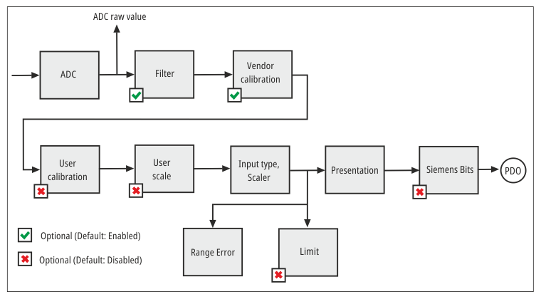 Fig.171: EL8601-8411 – data stream
Designation | CoE - Index | CoE - Name | Factory setting (default) | Meaning |
|---|---|---|---|---|
ADC raw value | 0x80AE:01 | ADC raw value |
| ADC raw value |
Filter | 0x80A0:06 | Enable filter | TRUE | Enable digital filter |
0x80A0:15 | Filter settings | 50 Hz FIR (2) | Select filter type | |
Vendor calibration | 0x80A0:0B | Enable vendor calibration | TRUE | Enable vendor calibration |
0x80AF:01 | Calibration offset | Parameter for vendor calibration | ||
User calibration | 0x80A0:0A | Enable user calibration | FALSE | Enable user calibration |
0x80A0:17 | User calibration offset | 0 | User calibration offset | |
0x80A0:18 | User calibration gain | 16384dec | User calibration gain | |
User scale | 0x80A0:01 | Enable user scale | FALSE | Enable user scale |
0x80A0:11 | User scale offset | 0 | User scale offset | |
0x80A0:12 | User scale gain | 65535 | User scale gain | |
Input type, Scaler | 0x80AD:01 | Input type | V ±10 V (2) | Selection of the measuring range |
0x80AD:12 | Scaler | Extended Range (0) | Select scaling type: | |
Range Error | 0x80AD:17 | Low Range Error | -32768dec | Lower error threshold, |
0x80AD:18 | High Range Error | 32768dec | Upper error threshold, | |
Limit | 0x80A0:07 | Enable Limit 1 | FALSE | Enable limit value monitoring for "Limit 1" |
0x80A0:08 | Enable Limit 2 | FALSE | Enable limit value monitoring for "Limit 2" | |
0x80A0:13 | Limit 1 | 0 | "Limit 1" for limit value monitoring | |
0x80A0:14 | Limit 2 | 0 | "Limit 2" for limit value monitoring | |
0x80A0:0E | Swap Limit bits | FALSE | Invert limit function | |
Presentation | 0x80A0:02 | Presentation | Signed (0) | Select data format of the measured values |
Siemens bits | 0x80A0:05 | Siemens bits | FALSE | Select Siemens output format |