CSP (position control)
CSP is the abbreviation for "Cyclic synchronous position".
A defined target position can be set via the "Target position" variable.
 | Minimum cycle time The cycle time in CSP modus must be 2^n * 125 µs (where n = 1 to 8), |
With the settings for the CSP operation mode, the terminal internally calculates the control loops for current, velocity and position. The NC calculates the setpoint for the position and transfers it to the terminal.
Following error monitor
Furthermore, there is an option in CSP mode to activate a following error monitor. The following error monitor is switched off on delivery. In all other modes this is not used and is ignored.
- The window of the following error monitor can be adjusted with the Following error window (Index 0x8010:50). The value set here – multiplied by the scaling factor – specifies by what position the actual position may differ from the set position, positively and negatively. The total accepted tolerance is thus twice as large as the position entered in the Following error window (see fig. Following error window).
- The time (in ms) allowed for a following error exceedance can be set with the Following error time out (Index 0x8010:51). As soon as the target position is exceeded by more than the position entered in the Following error window for the time entered in the Following error time out, the terminal outputs an error and stops immediately.
- The current following error can be read in the Following error actual value (Index 0x6010:06).
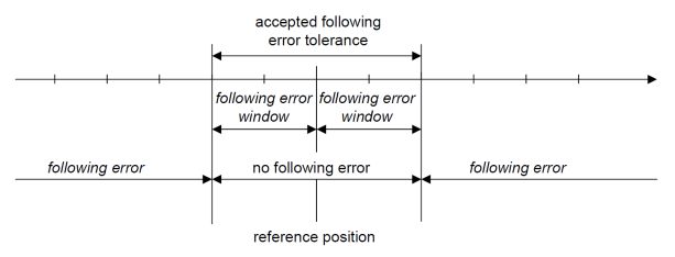
The value 0xFFFFFF (- 1) in the Following error window means that the following error monitor is switched off and corresponds to the delivery status.
The Following error time out is 0x0000 (0) on delivery.
Example of motion command with following error monitoring
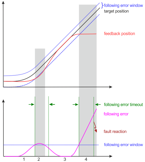
- 1. When accelerating, the following error increases.
- 2. The set limit value for the following error (following error window) is exceeded.
The duration of the exceedance of the following error window (shown in gray in the figure above) is shorter than the period specified in following error timeout (shown in green in the figure above). - No error is triggered.
- 3. The following error decreases to zero as soon as the target position is reached.
In the event of a blockage of the axis (e.g. end stop), target position continues to run, while feedback position stops. - The following error increases.
- 4. The following error exceeds the limit value Following error window for a longer period than specified in following error timeout.
- After expiration of following error timeout an error is triggered (fault reaction).