Commissioning with status word and control word
The operation modes CST, CSTCA, CSV and CSP can be used without TwinCAT NC.
Output stage enabled via the control word (index 0x7010:01)
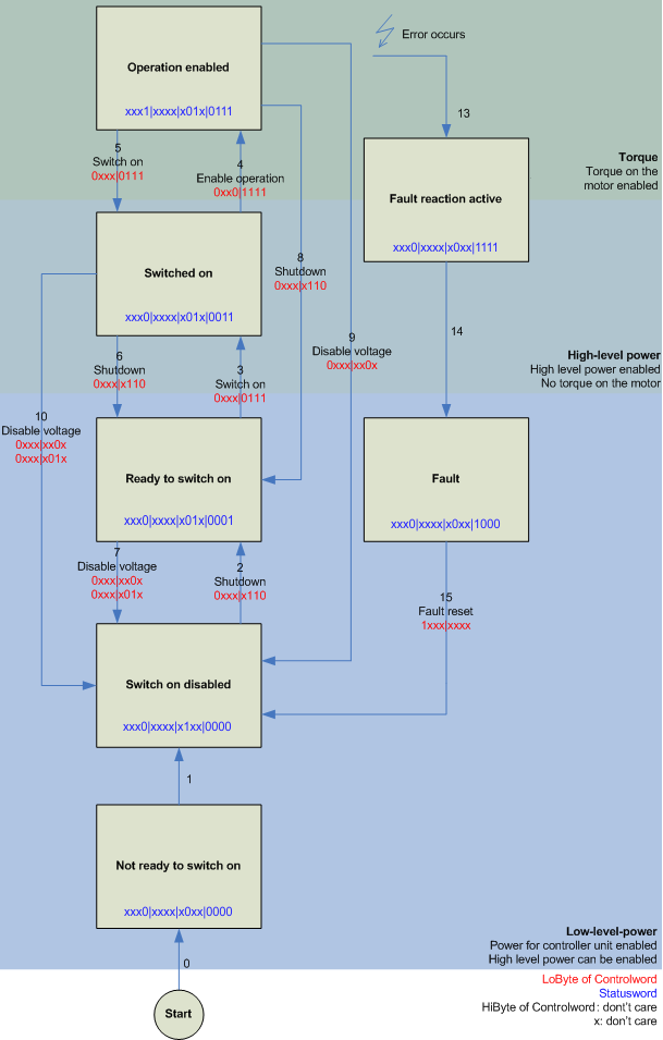
The output stage has to be enabled for each operation mode. To do this, the values specified in the following table at Enable output stage must be entered via the PLC in the control word in the specified order (1. - 5.) (according to the definition for the state machine see Fig. DS402 State Machine).
The bits of the high byte (CW.8 - CW.15) are reserved and not relevant for enabling the output stage.
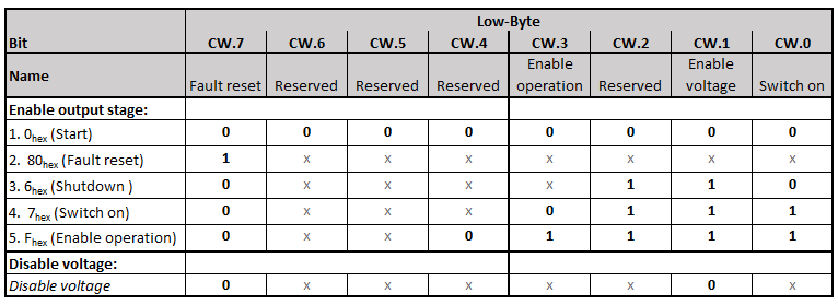
For the bits named "Reserved" further functions are defined according to the specifications for the state machine, which are not supported by the EL7411 (e. g. CW.2: "Quick stop (inverse)").
Checking the individual steps via the status word (0x6010:01)
The respective status messages are output in the status word.
 | Checking the status word mandatory It is mandatory to check after each input in the control word whether the internal state machine has followed the requirements of the control word (see also Fig. DS402 State Machine).
|
To enable the output stage, check whether the corresponding status messages 1. - 5. (Enable output stage) of the following table are displayed.
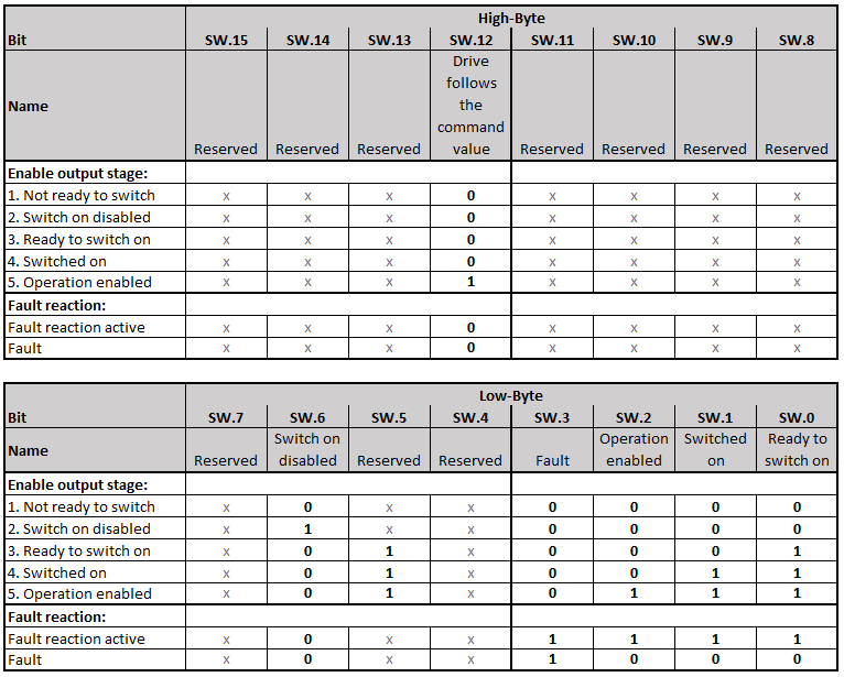
For the bits named "Reserved" further status messages are defined according to the specifications for the state machine, which are not supported by the EL7411 (e.g. SW.5: "Quick stop (inverse)").
CST - cyclic synchronous torque
Select "Cyclic synchronous torque mode" in index 0x7010:03 "Modes of operation". In the respective process data, the Predefined PDO Assignment "Torque" should also be selected. Afterwards the configuration must be reloaded to accept the selection.
Under the index 0x6010:03 "Modes of operation display" it can be checked in which mode the EL7411 actually is.
Via the PLC a defined torque can be defined in the variable "Target torque" as a basis for the EL7411 control. The torque is specified in 1000th of the nominal current. A value of 1000dec, for example, corresponds to the set index 0x8011:12 "Rated current". The value 1dec corresponds to one 1000th of the nominal current.
CSTCA - cyclic synchronous torque with commutation angle
Select "Cyclic synchronous torque mode with commutation angle" in index 0x7010:03 "Modes of operation". In the respective process data, the Predefined PDO Assignment "Torque" should also be selected. Afterwards the process data 0x1603 "DRV Commutation angle" can be added and the configuration must be reloaded to accept the selection.
Under the index 0x6010:03 "Modes of operation display" it can be checked in which mode the EL7411 actually is.
Via the PLC a defined torque can be set in the "Target torque" variable as a basis for the EL7411 control. In the "Commutation angle" variable the angle to be maintained with the set torque can be specified. The torque is specified in 1000th of the nominal current. A value of 1000dec, for example, corresponds to the set index 0x8011:12 "Rated current". The value 1dec corresponds to one 1000th of the nominal current. The angle value must be converted, 65536dec corresponds to an electrical angle of 360°.
CSV - cyclic synchronous velocity
Select "Cyclic synchronous velocity" in index 0x7010:03 "Modes of operation". In the respective process data, the Predefined PDO Assignment "Velocity" should also be selected. The configuration must then be reloaded to accept the selection.
Under the index 0x6010:03 "Modes of operation display" it can be checked in which mode the terminal actually is.
Via the PLC a defined speed can be set in the variable "Target velocity" 0x7010:06 as a basis for the terminal control. The constant value "Velocity encoder resolution" in CoE object 0x9010:14 corresponds to 1 revolution per second. If this value is entered under "Target velocity", the motor speed is 1 rpm. The velocity can be increased by entering a suitable multiple of the "Velocity encoder resolution" value under "Target velocity".
CSP - cyclic synchronous position
Select "Cyclic synchronous position" in index 0x7010:03 "Modes of operation". In the respective process data, the Predefined PDO Assignment "Position" should also be selected. The configuration must then be reloaded to accept the selection.
Under the index 0x6010:03 "Modes of operation display" it can be checked in which mode the servo terminal actually is.
Via the PLC a defined position can be set in the variable "Target position" 0x7010:05 to which the motor is to drive. The unit is increments. Depending on the feedback set, the number of increments per revolution is based, for example, on the number of pulses of the incremental encoder per revolution or the Hall sensor resolution of 65535 increments per revolution.