Touch Probe
Functional description
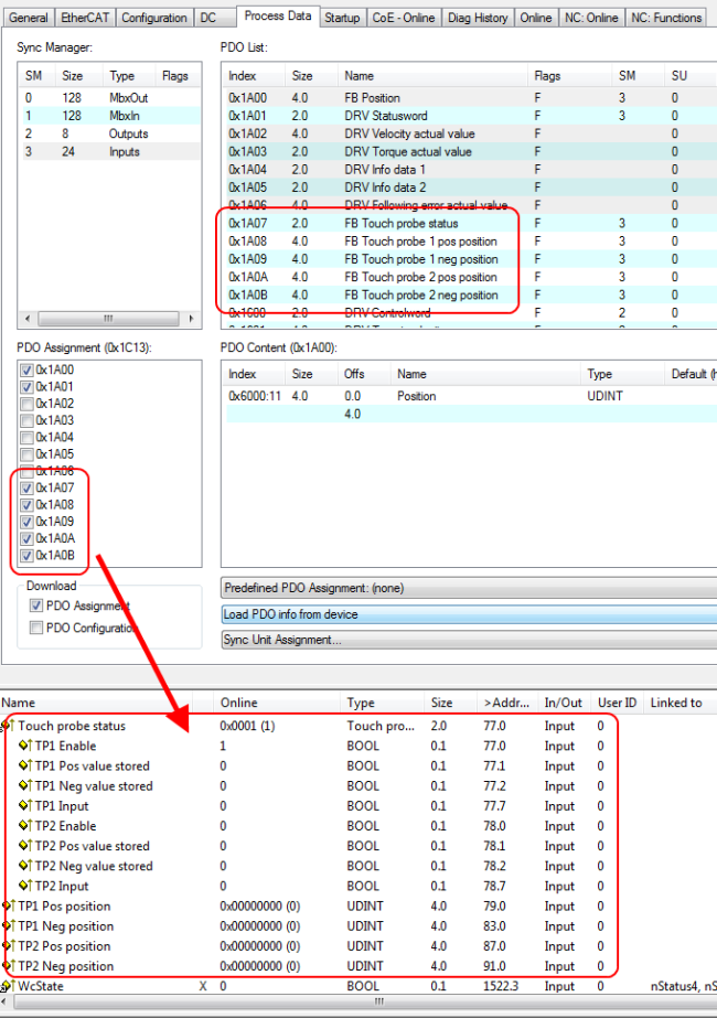
The "Touch Probe" function implemented in the EL7411 provides the user with the possibility to save the current position of the connected motor at a defined point in time. In the tab Process data the necessary inputs and outputs can be added.
The EL7411 has two digital inputs that can be used for the "Touch Probe" function. Each Touch Probe input can only detect edges of one direction at any time (rising or falling). It is not possible to react to both edges at the same time. However, there are no dependencies between the inputs (i.e. TP1 rising edge and TP2 falling edge is allowed).
The abbreviation TP1 stands for Touch Probe 1 and is linked to input 1 (terminal point 8). The abbreviation TP2 stands for Touch Probe 2 and is linked to input 2 (terminal 16) of the terminal. TP1 is used here as an example for the description of the function. The C-track of the incremental encoder can be selected as Touch Probe-trigger via the CoE parameter 0x8001:11 or 0x8001:12 "Touch probe x source" with the value "Hardware zero impulse (5)". However, this is not possible with the "Drive Motion Control" operation mode.
Step-by-step
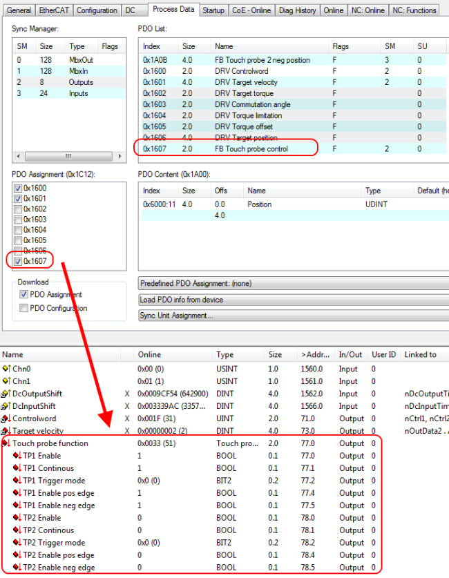
- "TP1 Enable" must be set to true in order to generally activate the Touch Probe function.
- Subsequently, you must decide whether the position is to be saved on a positive edge at input 1 ("TP1 Enable pos edge" = true) or on a negative edge ("TP1 Enable neg edge" = true).
- With "TP1 Continuous" is decided whether only at the first event the position should be stored ("TP1 Continuous" = false) or whether this should happen at every event ("TP1 Continuous" = true).
- For example, if "TP1 Continuous" and "TP1 Enablepos edge" are set, the position is saved on each rising edge at input 1 of the terminal.
- If "TP1 Enable neg edge" is set and "TP1 Continuous" is not set, the position will only be saved on the first negative edge at input 1 of the terminal. If you wish to repeat this procedure, you must first deactivate "TP1 Enable" and then activate it again. Then the position is saved again on the first negative edge.
- "TP1 Trigger mode" has no function in the case of the EL7411.
- The saved position of the positive edge can be read in the inputs of the process data under "TP1 Pos position", that of the negative edge under "TP1 Neg position".
- The variables under "Touch probe status" are for the diagnosis.
- The Touch Probe inputs must be addressed with a 1-wire +24 V signal.