Shielding concept
Together with the shield busbar, the prefabricated cables from Beckhoff Automation offer optimum protection against electromagnetic interference.
It is highly recommended to apply the shield as close as possible to the terminal, in order to minimize operational disturbances.
Connection of the motor cable to the shield busbar
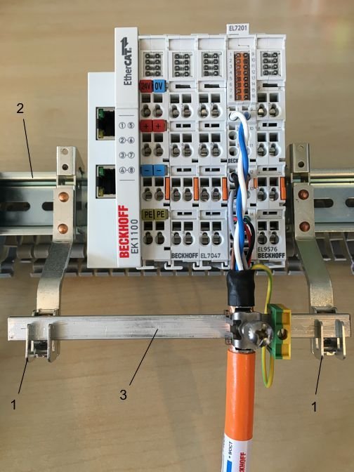
Fasten the shield busbar supports 1 to the DIN rail 2. The mounting rail 2 must be in contact with the metallic rear wall of the control cabinet over a wide area. Install the shield busbar 3 as shown below.
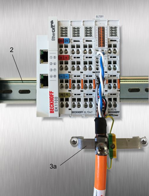
As an alternative, a shield busbar clamp 3a can be screwed directly to the metallic rear wall of the control cabinet (fig. “shield busbar clamp”)
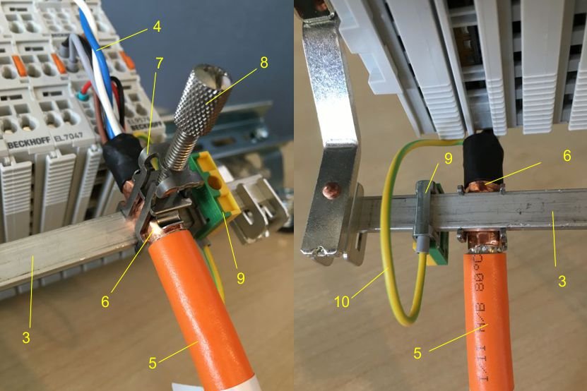
Connect the cores 4 of the motor cable 5, then attach the copper-sheathed end 6 of the motor cable 5 with the shield clamp 7 to the shield busbar 3 or shield busbar clamp 3a. Tighten the screw 8 to the stop.
Fasten the PE clamp 9 to the shield busbar 3 or shield busbar clamp 3a. Clamp the PE core 10 of the motor cable 5 under the PE clamp 9.
Connection of the feedback cable to the motor
 | Feedback cables Use shielded feedback cables. For differential signal types, it is recommended to twist the respective cores. |
When the feedback connector is screwed to the motor, the shield connection of the feedback cable is made via the metallic connector fastening.
On the terminal side the shield can also be connected. Wire the cores of the feedback cable and fasten the copper-sheathed end of the feedback cable to the shield busbar 3 or shield busbar bracket 3a using the shield clamp 7. The motor cable and the feedback cable can be connected to the shield clamp 7 with the screw 8.