EL7342 - LEDs and connection
| |
Risk of injury through electric shock and damage to the device! Bring the Bus Terminals system into a safe, de-energized state before starting mounting, disassembly or wiring of the Bus Terminals. |

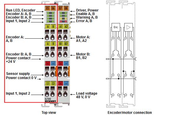 Fig.31: EL7342 LEDs and connection (left-hand section of the housing)
Notice | |
Fuse protection of the supply voltage The electrical protection of the load voltage must be selected in such a way that the maximum flowing current is limited to 3 times the rated current (max. 1 second)! |
EL7342 - Connection (left-hand section of the housing)
|
Terminal point |
Name |
Description |
|---|---|---|
|
1 |
Enc. A, A |
Encoder A-input A |
|
2 |
Enc. B, A |
Encoder B-input B |
|
3 |
Power Encoder +24 V |
+ 24 V, encoder supply (from positive power contact) |
|
4 |
Input 1 |
Digital input 1 (+24 VDC) or |
|
5 |
Enc. A, B |
Encoder A-input B |
|
6 |
Enc. B, B |
Encoder B-input B |
|
7 |
Power Encoder 0 V |
0 V, encoder supply (from negative power contact) |
|
8 |
Input 2 |
Digital input 2 (+24 VDC) or |
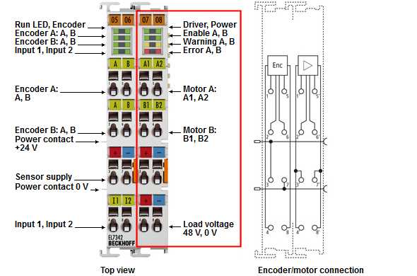 Fig.32: EL7342 - Connection (right -hand section of the housing)
EL7342 - Connection (right-hand section of the housing)
Terminal point | Name | Description |
|---|---|---|
1' | A1 | Motor A, motor winding A1 |
2' | B1 | Motor B, motor winding B1 |
3' | Power Motor +48 V | Motor supply feed (maximum +48 VDC) |
4' | Power Motor +48 V | Motor supply feed (maximum +48 VDC) |
5' | A2 | Motor A, motor winding A2 |
6' | B2 | Motor B, motor winding B2 |
7' | Power Motor 0 V | Motor supply feed (0 V) |
8' | Power Motor 0 V | Motor supply feed (0 V) |
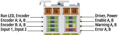 Fig.33: EL7342 - LEDs
EL7342 - LEDs (left prism)
LED | Color | Meaning | |
|---|---|---|---|
Run | green | This LED indicates the terminal's operating state. | |
off | State of the EtherCAT State Machine: INIT = terminal initialization | ||
flashing | State of the EtherCAT State Machine: PREOP = function of mailbox communication and variant standard settings | ||
single flash | State of the EtherCAT State Machine: SAFEOP = verification of the sync manager channels and the distributed clocks. | ||
on | State of the EtherCAT State Machine: OP = normal operating state; mailbox-and process data communication is possible | ||
flickering | State of the EtherCAT State Machine: BOOTSTRAP = function for terminal firmware updates | ||
Enc. A A | green | on | Signal at encoder A - input A. |
Enc. A B | green | on | Signal at encoder A - input B. |
Enc. B A | green | on | Signal at encoder B - input A. |
Enc. B B | green | on | Signal at encoder B - input B. |
Input 1 | green | on | Signal at digital input 1. |
Input 2 | green | on | Signal at digital input 2. |
EL7342 - LEDs (right prism)
LED | Color | Meaning | |
|---|---|---|---|
Motor Power | green | off | Supply voltage (48 VDC) not present or |
on | Supply voltage (48 VDC) present. | ||
Enable A | green | off | The motor control (motor A) is blocked or EL7342 is not ready for operation. |
on | The motor control (motor A) is activated or EL7342 is ready for operation. | ||
Enable B | green | off | The motor control (motor B) is blocked or EL7342 is not ready for operation. |
on | The motor control (motor B) is activated or EL7342 is ready for operation. | ||
Warning A/B | yellow | off | no defect |
on | Configuration error, e.g.: | ||
Error A | red | off | no defect |
on | Configuration error of output stage A, e.g.: | ||
Error B | red | off | no defect |
on | Configuration error of output stage B, e.g.: | ||