EL7047 - LEDs and connection
| |
WARNING! Risk of electric shock and damage of devices possible! Bring the bus terminal system into a safe, powered down state before starting installation, disassembly or wiring of the Bus Terminals! |

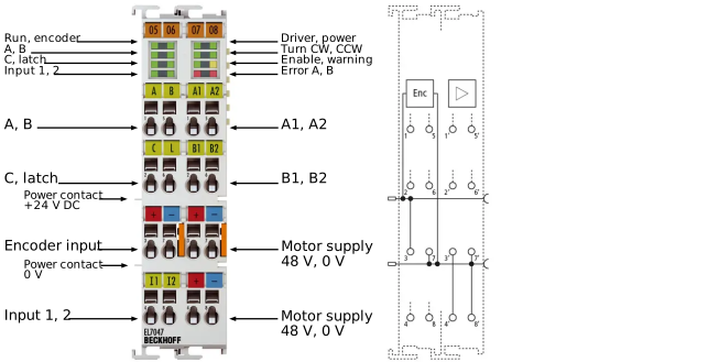 Fig.5: LEDs and Connection EL7047
Terminal Points - Left-hand section of the housing | ||
|---|---|---|
Terminal point | Name | Signal |
1 | A | Encoder input A |
2 | C | Encoder input C (zero input). If object 0x7000:01 is set in the control word and a rising edge occurs at encoder input C, the current counter value is stored as a reference mark in the latch register. |
3 | Encoder input | Encoder supply +24 V DC (from positive power contact) |
4 | Input 1 | Digital input 1 (24 V DC) |
5 | B | Encoder input B |
6 | Latch | Latch input. The current counter value is stored as a reference mark in the latch register, if object 0x7000:02 is set and a rising edge occurs at the latch input; or object 0x7000:04 is set and a falling edge occurs at the latch input. |
7 | Encoder input | Encoder supply 0 V (from negative power contact) |
8 | Input 2 | Digital input 2 (24 V DC), also configurable as digital output (0.5 A) |
Terminal Points - Right-hand section of the housing | ||
|---|---|---|
Terminal point | Name | Signal |
1' | A1 | Motor winding A1 |
2' | B1 | Motor winding B1 |
3' | Motor supply +48V | Feeding for output stage (max. +48 V DC) |
4' | Motor supply +48V | Feeding for output stage (max. +48 V DC) |
5' | A2 | Motor winding A2 |
6' | B2 | Motor winding B2 |
7' | Motor supply 0V | Feeding for output stage (0 V DC) |
8' | Motor supply 0V | Feeding for output stage (0 V DC) |
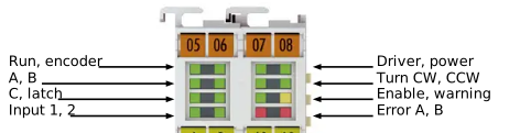 Fig.41: EL7047 - LEDs
LEDs (left prism) | |||
|---|---|---|---|
LED | Color | Meaning | |
RUN | green | This LED indicates the terminal's operating state: | |
off | State of the EtherCAT State Machine: INIT = Initialization of the terminal or BOOTSTRAP = Function for firmware updates of the terminal | ||
blinking | State of the EtherCAT State Machine: PREOP = Setting for mailbox communication and variant standard settings | ||
single flash | State of the EtherCAT State Machine: SAFEOP = Channel checking of the Sync Manager and the Distributed Clocks. Outputs stay in safe operation mode. | ||
on | State of the EtherCAT State Machine: OP = Normal operation mode, mailbox- and process data communication possible | ||
Encoder | green | on | Encoder ready for operation |
A | green | on | Signal at encoder input A |
B | green | on | Signal at encoder input B |
C | green | on | Signal at encoder input C |
Latch | green | on | Signal at latch input |
Input 1 | green | on | Signal at digital input 1 |
Input 2 | green | on | Signal at digital input 2 |
LEDs (right prism) | |||
|---|---|---|---|
LED | Color | Meaning | |
Driver | green | on | Driver stage ready for operation |
Power | green | off | The power supply voltage (48 V DC) is absent or |
on | The power supply voltage (48 V DC) is present | ||
Turn CW | green | on | Motor is triggered clock wise |
Turn CCW | green | on | Motor is triggered counter clock wise |
Enable | green | off | The motor control is blocked (Index 0x6010:02 is not set) or EL7047 is not ready for operation |
on | The motor control is activated (Index 0x6010:02 is set) or EL7047 is ready for operation | ||
Warning | yellow | off | No errors |
on | Configuration error, e.g.:
| ||
Error A | red | on | Configuration error of output stage A, e.g.:
|
Error B | red | on | Configuration error of output stage B, e.g.:
|