Digital input emulation
The EL7031-0030 offers the option to use analog inputs as digital inputs. To this end, in the first step enable digital input emulation for the required analog input via index 0x8012:45 Digital input emulation 1 (for input 1) and/or index 0x8012:49 Digital input emulation 2 (for input 2) (see Figure).
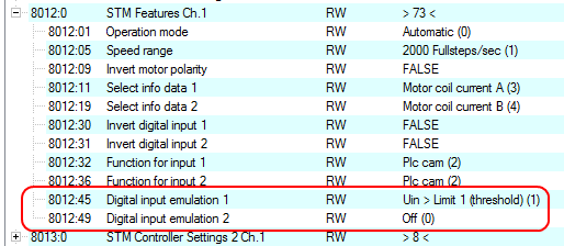 Fig.177: Enable digital input emulation
The following table shows the available functions:
Value | Function | Description |
|---|---|---|
0 | Off | Function disabled |
1 | Uin > Limit 1 (threshold) | The analog measured value is greater than limit 1 |
2 | Uin > Limit 2 (threshold) | The analog measured value is greater than limit 2 |
3 | Limit 1 < Uin < Limit 2 (band) | The analog measured value is greater than limit 1 and less than limit 2 |
4 | Limit 2 < Uin < Limit 1 (band) | The analog measured value is greater than limit 2 and less than limit 1 |
5 | Uin > Limit 1 = 1; | The digital input is set to ‘1’, if the measured value is greater than limit 1. |
6 | Uin > Limit 2 = 1; | The digital input is set to ‘1’, if the measured value is greater than limit 2. |
Limit 1, which is required for the corresponding function, then has to be enabled via index 0x8030:07 Enable limit 1 (for input 1) or index 0x8040:07 Enable limit 1 (for input 2) and/or limit 2 via index 0x8030:08 Enable limit 2 (for input 1) or index 0x8070:08 Enable limit 2 (for input 2) (see Figure).
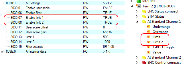 Fig.178: Enable limits
Finally, the threshold value, from which the parameterized emulation switches the digital input 1 or 2 in the PDO, hast to be set for limit 1 via index 0x8030:13 Limit 1 (for input 1) or index 0x8040:13 Limit 1 (for input 2) and/or for limit 2 via index 0x8030:14 Limit 2 (for input 1) or index 0x8040:14 Limit 2 (for input 2) (see Figure).
0dec corresponds to 0 V and 32767dec corresponds to 10 V.
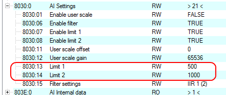 Fig.179: Adjusting the threshold value for the limits
If the set threshold value is exceeded, Digital input 1 or Digital input 2 issues a high-level signal, which can be read from the cyclic process image (see Figure).
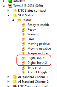 Fig.180: Digital inputs in the process image
Digital input 1 is also the signal for the external latch in the encoder profile (“Status of external latch”).
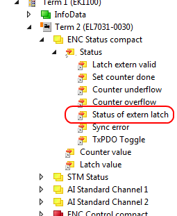 Fig.181: Status of external latch in the process image