LEDs and connection
| |
Risk of injury through electric shock and damage to the device! Bring the Bus Terminals system into a safe, de-energized state before starting mounting, disassembly or wiring of the Bus Terminals. |

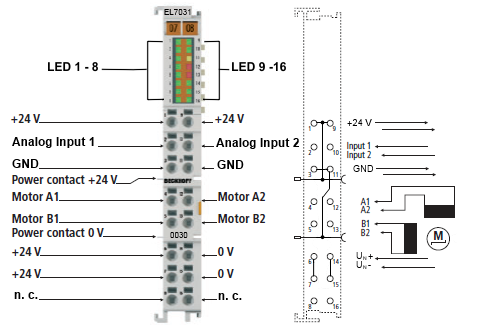 Fig.27: LEDs and connection EL7031-0030
Connection
Terminal point | Name | Signal |
|---|---|---|
1 | +24 V | +24 VDC, internally connected with positive power contact and pin 9 |
2 | Analog Input 1 | Analog Input 1 (0-10 VDC) |
3 | GND | 0 VDC, internally connected with negative power contact and pin 11 |
4 | A1 | Motor winding A |
5 | B1 | Motor winding B |
6 | +24 V | Supply voltage load 24 V |
7 | +24 V | Supply voltage load 24 V |
8 | n. c. | n.c. |
9 | +24 V | +24 VDC, internally connected with positive power contact and pin 1 |
10 | Analog Input 2 | Analog Input 2 (0-10 VDC) |
11 | GND | 0 VDC, internally connected with negative power contact and pin 3 |
12 | A2 | Motor winding A |
13 | B2 | Motor winding B |
14 | 0 V | Supply voltage load 0 V |
15 | 0 V | Supply voltage load 0 V |
16 | n. c. | n.c. |
LEDs
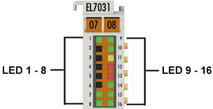 Fig.28: EL7031-0030-LEDs
No. | LED | Color | Meaning | |
|---|---|---|---|---|
1 | RUN | green | This LED indicates the terminal's operating state: | |
off | State of the EtherCAT State Machine: INIT = initialization of the terminal or BOOTSTRAP = function for firmware updates of the terminal | |||
flashing | State of the EtherCAT State Machine: PREOP = function for mailbox communication and different standard-settings set | |||
single flash | State of the EtherCAT State Machine: SAFEOP = verification of the Sync Manager channels and the distributed clocks. | |||
on | State of the EtherCAT State Machine: OP = normal operating state; mailbox and process data communication is possible | |||
2 | - | - | - | - |
3 | - | - | - | - |
4 | - | - | - | - |
5 | - | - | - | - |
6 | - | - | - | - |
7 | Turn CW | green | on | Motor turns clockwise |
8 | Input 1 | green | on | Signal at analog input 1 |
9 | Driver | green | on | Driver stage ready |
10 | Power | green | off | Supply voltage (24 VDC) not available or |
on | Supply voltage (24 VDC) available | |||
11 | Warning | yellow | off | no defect |
on | Configuration error, e.g.:
| |||
12 | Error A | red | on | Configuration error of output stage A, e.g.:
|
13 | Error B | red | on | Configuration error of output stage B, e.g.:
|
14 | Enable | green | off | Motor control is blocked (index 0x6010:02 is not set) or EL7031-0030 is not ready for operation |
on | Motor control is activated (index 0x6010:02 is set) or EL7031 is ready for operation | |||
15 | Turn CCW | green | on | Motor turns counter-clockwise |
16 | Input 2 | green | on | Signal at analog input 2 |