NC settings
Reference velocity selection
The maximum velocity can be calculated from the base frequency and the motor frequency.
vmax = base frequency / motor frequency = (2000 full steps / s) / (200 full steps / rev) = 10 revolutions / s
The reference velocity can be calculated by multiplying the maximum velocity with the distance per revolution.
vref = 10 revolutions / s x 360° = 3600 °/ s
 Fig.156: Reference velocity parameter
 Dead time compensation
The dead time compensation can be adjusted on the Time Compensation tab of Axis1_ENC.
It should theoretically be 3 cycles of the NC cycle time, although in practice 4 cycles are preferable.
Therefore, the settings of the parameters Time Compensation Mode Encoder should be ‚ON (with velocity)‘ and Encoder Delay in Cycles ‘4’.
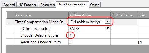 Fig.157: Dead time compensation parameter
 Scaling factor
The scaling factor can be changed by selecting "Axis 1_Enc" and tab "Parameter" in the NC (see Setting the Scaling Factor). The value can be calculated with the formulas specified below.
 Fig.158: Setting the Scaling Factor
Calculation of the scaling factor
with encoder, 4-fold evaluation:
SF = distance per revolution / (increments x 4) = 360° / (1024 x 4) = 0.087890625 ° / INC
without encoder:
SF = distance per revolution / (full steps x microsteps) = 360° / (200 x 64) = 0.028125 ° / INC
Position lag monitoring
The position lag monitoring function checks whether the current position lag of an axis has exceeded the limit value. The position lag is the difference between the set value (control value) and the actual value reported back. If the terminal parameters are set inadequately, the position lag monitoring function may report an error when the axis is moved. During commissioning it may therefore be advisable to increase the limits of the Position lag monitoring slightly.
Notice | |
ATTENTION: Damage to equipment, machines and peripheral components possible! Setting the position lag monitoring parameters too high may result in damage to equipment, machines and peripheral components. |
 Fig.159: Position lag monitoring parameters
Kv factors
In the NC two proportional factors Kv can be set under "Axis 1_Ctrl " in tab "Parameter". First select the position controller Type with two P constants (with Ka) under the “NC Controller” tab. The two P constants are for the Standstill range and for the Moving range (see Fig. Setting the proportional factor KV). The factors can be used to set the start-up torque and the braking torque to a different value than the drive torque. The threshold value can be set directly below (Position control: Velocity threshold V dyn) between 0.0 (0 %) and 1.0 (100 %). Fig. Velocity ramp with KV factor limit values shows a speed ramp with thresholds of 30 %. The Kv factor for Standstill (t1 and t3) can be different than the Kv factor for Moving (t2). In this case the same factor was used, since for stepper motors this function is less crucial than for DC motors.
 Fig.160: Speed ramp with KV factor limit values
 Fig.161: Setting the proportional factor KV
Dead band for position errors
Microstepping can be used to target 200 * 64 = 12800 positions. Since the encoder can only scan 1024 * 4 = 4096 positions, positions between two encoder scan points may not be picked up correctly, in which case the terminal will control around this position The dead band for position errors is a tolerance range within which the position is regarded as "reached" (Fig. Dead band for position errors).
 Fig.162: Dead band for position errors
Setting the acceleration time
In order to pass through any resonances that may occur as quickly as possible, the ramps for the acceleration time and the deceleration time should be as steep as possible.
 Fig.163: Setting the acceleration time on the "Dynamics" tab
Notice | |
ATTENTION: Use a buffer capacitor terminal (EL9570) for short deceleration ramps. Very short deceleration ramps may lead to temporarily increased feedback. In this case the terminal would report an error. To prevent this, one should connect a buffer capacitor terminal (EL9570) with a suitable ballast resistance (e.g. 10 Ohm) in parallel with the power supply of the motor (50 V) in order to absorb energy being fed back. |