Example 2
In the second example, a DC charging session is set up with the Beckhoff EL6761 EtherCAT Terminal and high-level communication.
The Sevenstax V2G Simulator was used to test the implementation. The simulator is connected to the EL6761 terminal via the CP connection. In addition, the power supply is provided via one of the USB interfaces. The LAN interface enables interaction with the simulator via HTTP.
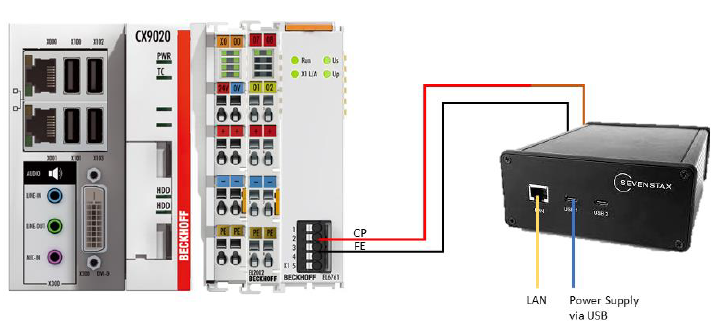 Fig.92: Exemplary setup 2 using the Sevenstax simulator
To use the terminal for high-level communication, the predefined PDO setting "DC High Level" is selected.
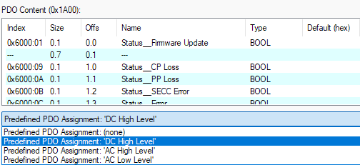 Fig.93: Predefined PDO "DC High Level"
In addition, the terminal is configured via CoE Index 8000 (SECC settings) as shown in the "Index 8000 settings" figure.
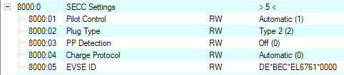 Fig.90: Index 8000 settings
For the transmission of high-level communication, the terminal uses an extended state machine, which is provided via the state machine state PDO.
Here too, the state transitions between the state machine states are performed by the terminal, and the application must process the states in the TwinCAT PLC. The states are shown below.
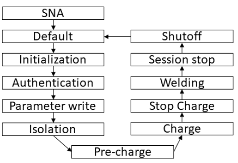 Fig.95: State sequence of the state machine
After starting, the application initializes its outputs to defined values (SNA state), reaches the default state and remains there until the EV is connected.
When the EV is connected, the application must set current limits (minimum, maximum, ripple and regulation tolerance) as well as voltage and power limits. In addition, the responses for the processing of CA (Control Authentication), CPD (Control Parameters) and CC (Control Isolation) must be set to "ongoing" as they have not yet been completed.
In the following authentication step, the CA response is set to completed. In the parameter step, this is repeated for the CPD response and for the CC response in the "Isolation" state. In addition, the isolation step sets the current and voltage PDOs to zero to enable "ramping" in the following state.