IEC 61851 - Low-level communication
The standard is divided into several parts, each of which focuses on a different aspect of charging electric vehicles:
- IEC 61851-1: This part contains general requirements for conductive charging systems for electric vehicles and covers the basic topics of safety, functionality and interoperability.
- IEC 61851-21: This part deals with the requirements for electric vehicles for conductive connection to an AC/DC supply. It is further divided into two parts:
- IEC 61851-21-1: Covers on-board measuring devices for electric vehicles (EV) for measuring the electricity transmitted from the grid to the vehicle.
- IEC 61851-21-2: Focuses on the requirements for the vehicle's internal power supply circuit for connection to the charging station.
- IEC 61851-22: This part specifies the requirements for the charging station for electric vehicles and outlines the testing and safety requirements for the equipment.
- IEC 61851-23: This part defines the digital communication between the electric vehicle and the electric vehicle supply device for DC charging.
- IEC 61851-24: This part deals with digital communication between a DC EV charging station and an electric vehicle to control DC charging.
The IEC 61851 standard is of central importance in ensuring that charging stations and vehicles for electric vehicles are compatible and safe across manufacturers and countries. It aims to promote the widespread introduction of electric vehicles by providing a standardized framework for the charging infrastructure. For this reason, it has fixed four charging modes (see table Charging modes)
Charging modes table
Charging mode | Description |
|---|---|
Charging mode 1 | In this mode, the EV is connected directly to a household socket. |
Charging mode 2 | A special charging cable equipped with an internal cable control and protection device (IC-CPD) is used for charging mode 2. |
Charging mode 3 | In this mode, a special EVSE is used together with the EV on-board charger. The alternating current from the charging station is forwarded to the on-board circuit to charge the battery. To ensure public safety, several control and protection functions are used, including checking the protective earth and the connection between the EVSE and EV. |
Charging mode 4 | This is the only charging mode that includes an external charger with a DC output. The direct current is supplied directly to the battery and the on-board charger is bypassed. This mode can supply several hundred volts DC with a maximum current of 400 A. The high performance in this mode requires a higher level of communication and more stringent security features. |
As far as the primary communication between the EVSE and the EV is concerned, IEC 61851-1 specifies state-based communication via the CP connection contact. The PP connection provides information on the capacity of the line between EVSE, as well as information on whether a car or cable is plugged in.
This state-based communication on the CP connection provides for six states at different voltage levels that represent the charging readiness of the EVSE and EV. The states are listed in the IEC 61851 communication states table below.
Table IEC 61851 Communication states
State | CP voltage level | Description |
|---|---|---|
State A | + 12 V | EV not connected |
State B | + 9 V | EV connected; EV not ready |
State C | +6 V | EV connected; EV ready for charging; without ventilation |
State D | +3 V | EV connected; EV ready for charging; with ventilation |
State E | +0 V | Error state (e.g. lack of energy from the grid) |
State F | -12 V | Forced by the charging station, e.g. due to maintenance work |
In addition to the various voltage levels, the ESVE supplies a PWM signal with a specific duty cycle. An overview of the different duty cycle levels specified by IEC 61851 is shown below.
Table IEC 61851 Duty cycle
Duty Cycle D in % | Maximum permissible current | Description |
|---|---|---|
D < 3 % | 0 A | Invalid |
3 % ≤ D ≤ 7 % | HLC | A nominal duty cycle of 5% indicates high-level communication in accordance with ISO 15118 / DIN 70121. |
7 % ≤ D < 8 % | 0 A | Invalid |
8 % ≤ D < 10 % | 6 A | Some vehicles use this duty cycle to use a low current of D x 0.6 A, i.e. 4.8 A to 6 A. |
10 % ≤ D ≤ 85 % | D x 0.6 A | 6 A to 51 A |
85 % < D ≤ 96 % | (D - 64) x 2.5 A | 51 A to 80 A |
96 % < D ≤ 97 % | 80 A | Maximum value |
97 % < D ≤ 100 % | 0 A | Invalid |
After the EL6761 has recognized that the CP line is connected to the EV, the customer has the option of manipulating the PWM via 0x7001:16 Setpoint Current.
Setting the signal to "0" results in a PWM of 0% and charging is not possible. The value can only be set prior to plugging in to indicate that the EVSE is in maintenance mode. Any other valid value for this signal results in a PWM of 100 % if the EVSE is not connected.
If the terminal is connected to an EV, setting the signal to "1" results in a PWM of 100 %, while setting the signal to "2" HLC results in AC high-level communication (PWM of 5 %). Any value between "2" and "60" is ignored. Any value between "60" and "800" is calculated according to the table above and values above "800" are ignored.
The unit of this value is [A] with a factor of 0.1 of the values (from 60 to 800). If the signal is set to "0" during the charging process, the charging process is aborted. However, the charging process can be resumed at any time by setting 0x7001:16 Setpoint Current to a valid value without having to remove the plug.
Example: If the value "250" is sent via 0x7001:16 Setpoint Current, this means a maximum current of 25 A per phase and corresponds to a duty cycle of 41 % according to the calculation in the previous table. The duty cycle is then automatically calculated and set by the terminal.
To establish a charging connection between EVSE and EV, the figure below shows an exemplary communication process.
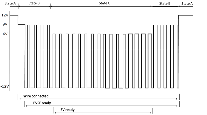 Fig.84: IEC 61851 Communication example. The charging power can be adjusted by changing the duty cycle in state C (see table "IEC 61851 Communication states"