Modular Device Profil Mapping of EL6751 (MDP)
The MDP mapping mode for the EL6751 is activated via the "EtherCAT" tab of the CANopen device.
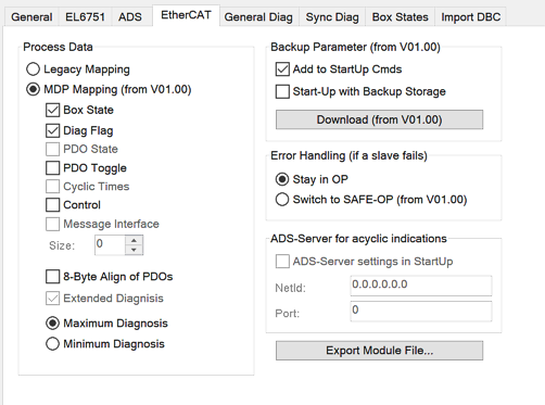 Fig.121: EtherCAT tab: Activate MDP Mapping Mode
If the "MDP Mapping (from V01.00)" radio button is activated, the following mapping options of the process image are available for selection:
Box State
This option extends the input process image by the "NodeState" of a box.
See Index F102 Node State.
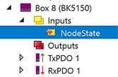 Fig.122: Variable NoteState
Diag Flag
This option extends the input process image by the "Diag Flag" of a box.
See Index F103 CANopen Diag Flag.
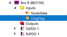 Fig.123: Variable DiagFlag
PDO Toggle (/PDO State)
In order to use this option, you have to additionally set a selection at "PDO-Toggle/PDO-State" in the characteristics of the desired TxPDO.
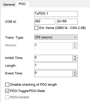 Fig.124: PDO tab: Set PDO toggle selection
If the "PDOToggle" option is selected in the MDP Diaglog, the input process image is extended by the PDOToggle bit varibale.
See Index 6004-67E4 CAN TxPDOs Toggle Node.
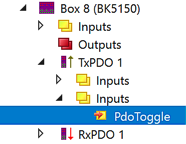 Fig.125: Variable PDOToggle
If the "PDOToggle" - option is not selected in the MDP Diaglog, the selection "PDO-Toggle/PDO-State" for TxPDO extends the input process image by the PDOState bit varibale.
See Index Index 6008-67E8 CAN TxPDOs PDOState.
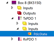 Fig.126: Variable PDOState
Control
This option adds the "control flags" to the output process image.
See Index F200 Control.
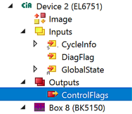 Fig.127: Variable ControlFlags
8-Byte Align of PDOs
If this option is set, each CAN PDO occupies 8 bytes in the EtherCAT process data, even if it is smaller than 8 bytes.
If this option is not set, the CAN PDOs in the EtherCAT process data are appended one after the other.
Maximum / Minimum Diagnosis
The minimal diagnosis contains objects from the CAN state (object 0xF108).
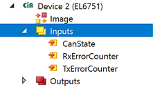 Fig.128: Minimum diagnosis
The maximum diagnosis is extended and contains objects from the CAN status (Object 0xF108) and the diagnosis of the CANopen Master (Object 0x101).
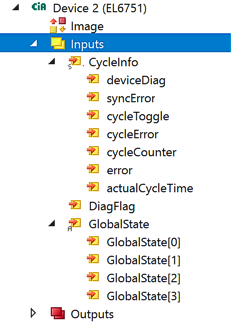 Fig.129: Maximum Diagnosis