Synchronization
In the EL 6751, the CAN cycle is synchronized with the EtherCAT cycle. Synchronization takes place by default via the Sync Manager 2 event or, if there is no EtherCAT output process data, via the Sync Manager 3 event. Alternatively, the EL6751 can also be operated in the Distributed Clocks mode, in which case synchronization takes place via the SNYC0 and SYNC1 events.
CAN cycle (Sync Multiplier = 1)
The following flow chart shows the sequence of the CAN cycle if a CAN cycle is also executed with each EtherCAT cycle (Sync Multiplier = 1 (0x1C32:02 == 0xF800:04 or 0x1C32:02 == 0 (default) or 0xF800:04 == 0)). If the cycle time of the EtherCAT master (0x1C32:05) is not transmitted in the StartUp SDOs (or the Backup Parameter Storage object) and no Distributed Clocks mode is set, then 0x1C32:05 = 0 and, hence, the Sync Multiplier = 1.
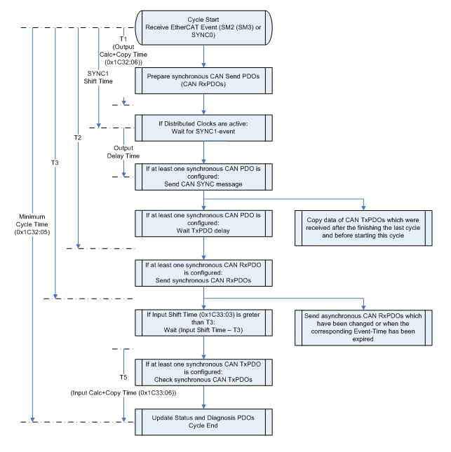 Fig.133: Flow chart for CAN cycle (Sync Multiplier = 1)
Synchronization with SM2 (SM3) event
When receiving the EtherCAT process data telegram, the SM2 event (SM3 if no EtherCAT output data are configured, i.e. only CANopen slaves without CAN RxPDOs) is generated by the EtherCAT slave controller, thus starting the CAN cycle. If synchronous CAN PDOs are configured, they will be dealt with at the beginning. Following the preparation of CAN transmit PDOs, the SYNC message will initially be sent. Because some CANopen slaves react strangely if their RxPDOs are received before they have sent their TxPDOs, a delay can be set for the TxPDOs in 0xF800:0E. After sending the SYNC message, the EL6751 waits until this delay has expired before sending any further CAN messages. After that, the synchronous RxPDOs are transmitted first, followed by the asynchronous RxPDOs (if they have changed or if the event time has expired). If the synchronous RxPDOs have been sent, the expiry of the input shift time is waited for. Subsequently, the receipt of the synchronous TxPDOs is checked. If the transmission type of a TxPDO is set to 1, the EL6751 expects a RxPDO in each cycle until the time T4; if this has not been received, the Node State of the CANopen slave (0xF102:yy) is set to 0x28 for one cycle. If the next SM2 (SM3) event is received before the CAN cycle is completed, the Cycle Exceed counter (0x1C32:0B or 0x1C33:0B) is incremented and a CAN cycle is omitted.
If only asynchronous PDOs are configured, then the process is much simpler. After receiving the SM2 event, the asynchronous CAN RxPDOs to be sent are determined (data has changed or event time has expired) and sent. Then the CAN TxPDOs received since the end of the last cycle are copied to the EtherCAT input data. If the Sync Managers 2 and 3 are set to 1-buffer mode and the input shift time is not equal to 0, the copying of the status and diagnosis to the EtherCAT input data is delayed until this time has expired. The advantage of this is that CAN TxPDOs received within this time window can be copied directly into the EtherCAT input data. However, care must be taken when setting the input shift time to ensure that the EtherCAT input data can be copied completely before the next EtherCAT cycle begins, otherwise the working the counter would not be okay.
Synchronization with SYNC0/SYNC1 event
The Distributed Clocks mode only makes sense if synchronous CAN PDOs are present. In this case, the CAN cycle is started by the SYNC0 event. The sending of the SYNC message is delayed until the SYNC1 event occurs, so that the SYNC message is sent with a jitter of maximum 500 ns. The remaining sequence of the CAN cycle corresponds to that in the case of synchronization with SM2 event.
CAN cycle (Sync Multiplier > 1)
The following flow chart shows the sequence of the CAN cycle if a CAN cycle is also executed with every nth EtherCAT cycle (n > 1) (Sync Multiplier > 1 (n*0x1C32:02 == 0xF800:04 and 0x1C32:02 != 0 and 0xF800:04 != 0)). If no Distributed Clocks mode is set, then the cycle time of the EtherCAT master (0x1C32:02) must be transmitted in the StartUp SDOs (or the Backup Parameter Storage object).
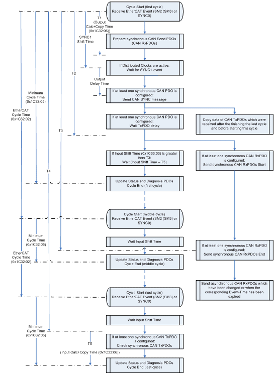 Fig.134: Flow chart for CAN cycle (Sync Multiplier > 1)
Synchronization with SM2 (SM3) event
Whereas in operating mode Sync Multiplier = 1 the synchronous RxPDOs must be sent completely before the EtherCAT input data is updated, this can extend over n EtherCAT cycles in operation with Sync Multiplier = n. The beginning of the CAN cycle is still the same as in operation with Sync Multiplier = 1. After the TxPDO delay has expired (on the flow chart it is assumed that the TxPDO delay is smaller than the input shift time), transmission of the synchronous RxPDOs begins. If the input shift time expires during that time, the EtherCAT input data containing the most recent data from all TxPDOs received up to this time is updated. After that, the next event is waited for each time until the last EtherCAT cycle within the CAN cycle is reached. In the middle EtherCAT cycles, the data of the asynchronous RxPDOs to be sent always receive the latest value, whereas the data of the synchronous RxPDOs are only updated in the first EtherCAT cycle. In the last EtherCAT cycle, the synchronous RxPDOs are checked following the expiry of the input shift time (as in operation with Sync Multiplier = 1). A Sync Multiplier > 1 is ineffective if only asynchronous PDOs are configured.
Synchronization with SYNC0/SYNC1 event
If distributed clocks are switched on, the CAN cycle would be started by the SYNC0 event. The sending of the SYNC message is delayed until the SYNC1 event occurs, so that the SYNC message is sent with a jitter of maximum 500 ns. The remaining sequence of the CAN cycle corresponds to that in the case of synchronization with SM2 event.