Interbus - introduction
Introduction to the system
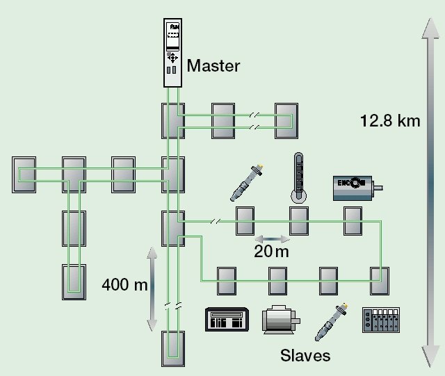
The Interbus system is configured as a data ring with a central master/slave access procedure. It has the structure of a spatial distributed shift register. Each device, with its registers of different length, is part of the shift register ring. The master pushes data through the ring serially. The use of the ring structure offers the option of sending and receiving data simultaneously. The two data directions of the ring are located in a single cable. Each Interbus system device has an ID register (identification register). This register contains information about the module type, the number of input and output registers, and status and error conditions. The Interbus system basically knows two operating modes:
- The ID cycle,
which is carried out for the initialization of the Interbus system and on demand. In the ID cycle, the coupling module reads the ID registers of all devices attached to the bus system and uses this information to build the process image. - The data cycle;
this is the actual duty cycle dealing with the data transmission. In the data cycle, the input data are transferred from the registers to the coupling module, and the output data from the coupling module the devices.
System configuration and device types
The Interbus club has a large number of different ID codes. Apart from 6 ID codes, Phoenix Contact has assigned these ID codes to couplers with digital and analog periphery. The manufacturer can therefore not be identified via the ID code. (Detailed commentary in Chapter "ID code and ID length"). The handling of the BK4xx0/BC4xx0 Interbus couplers does not differ from the equipment of other manufacturers.