PROFIBUS Connection
M12 round connector
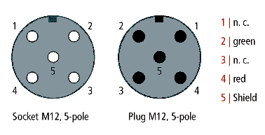
The M12 socket is inverse-coded and has five pins. Pin 1 transfers 5 VDC, pin 3 transfers GND for the active termination resistor. These must never be misused for other functions, as this can lead to destruction of the device.
Pins 2 and 4 transfer the PROFIBUS signals. These must never be swapped over, as this will prevent communication. Pin 5 transfers the shield, which is capacitively connected to the base of the Fieldbus Box.
Pin assignment M12 socket (-B310)
Pin assignment M12 socket/plug connector (-B318)
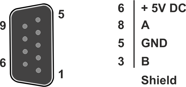
Nine-pin D-Sub
Pin 6 transfers 5 VDC, pin 5 transfers GND for the active termination resistor. These must never be misused for other functions, as this can lead to destruction of the device.
Pins 3 and 8 transfer the PROFIBUS signals. These must never be swapped over, as this will prevent communication.
Pin assignment of the PROFIBUS D-sub socket
PROFIBUS wire colors
|
PROFIBUS line |
M12 |
D-Sub |
|---|---|---|
|
B red |
Pin 4 |
Pin 3 |
|
A green |
Pin 2 |
Pin 8 |
Connection of the Fieldbus Box modules
The Fieldbus Box modules are connected either directly or via a T-piece (or Y-piece).
The B318 series features a socket and a plug connector, i.e. this is where the PROFIBUS is routed in the module. The supply voltage (+5 VDC) for the termination resistor is only present at the socket. The termination resistor ZS1000-1610 is only available as a plug connector.
The incoming PROFIBUS line should always end with a socket.
Two T-pieces are available:
- ZS1031-2600 with +5 VDC transfer for supplying the termination resistor
- ZS1031-2610 without +5 VDC transfer