FDL interface
The FDL protocol is the basic protocol on which every PROFIBUS protocol is based. FDL is the layer 2 implementation of PROFIBUS.
The FDL interface can be used to send FDL telegrams and pick up received FDL telegrams via ADS. This functionality is supported by the FC31xx from V02.66 and the EL6731 from V01.06.
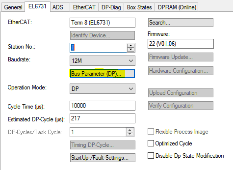
To use the FDL interface, the multi-master operation must be activated in the master.
To do this, click on "Bus-Parameter (DP)":
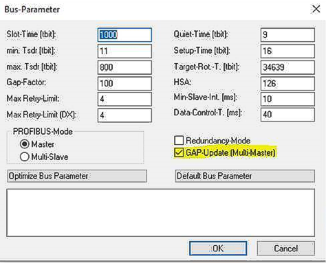
Activate the multi-master operation:
Now activate the FDL interface via ADS-Write:
ADS-Write parameters | Meaning |
|---|---|
Net-ID | Net-ID of the master (see the device's ADS tab) |
Port | 200 |
IndexGroup | 0xF400 |
IndexOffset | 0 |
Length | 1 |
Data | 0xFF (or the PB own address) |
Data: 0xFF, all data are received, as well as the global control telegram. With the specification of the own PB address only data of the own PB address are copied into the buffer.
FDL receive
With ADS-Read, FDL indications received from another master or locally generated FDL confirmations are retrieved according to the length. For each FDL request sent, an FDL confirmation is returned.
Here the buffer must be polled by ADS READ to read data, if the data length is 1 with the data content 0x00 there is no data in the buffer. The buffer is 0x4000 bytes large; if more data is received, it is lost.
Example to write data (here 8 bytes of data are sent from master 01 to master 02):
FDL_DataSend: ARRAY[0..15] OF BYTE := [16#01,16#00,16#82,16#81,16#0C,16#0A,16#21,16#20,16#01,16#02,16#03,16#04,16#05,16#06,16#07,16#08];
FDL_DataSend[0] | 0x01 | Cmd: Request |
FDL_DataSend[1] | 0x00 | Request |
FDL_DataSend[2] | 0x82 | Target PB address here Master address 2 (+ 0x80) |
FDL_DataSend[3] | 0x81 | Source PB address here Master address 1 (+ 0x80) |
FDL_DataSend[4] | 0x0C | SRD low (Send and Request data) |
FDL_DataSend[5] | 0x0A | Length of the data, counted from the following byte, here 10 byte |
FDL_DataSend[6] | 0x21 | DSAP |
FDL_DataSend[7] | 0x20 | SSAP |
FDL_DataSend[8..15] | 0x01,..0x08 | Data |
Send FDL data:
ADS-Write parameters | Meaning |
|---|---|
Net-ID | Net-ID of the master (see the device's ADS tab) |
Port | 200 |
IndexGroup | 0xF400 |
IndexOffset | 0 |
Length | Length of the data bytes of the ADS write command |
Data | FDL + Data |
Note: The length of the ADS must always be even. If the PB telegram has an odd length, set the length of the ADS to +1 to obtain an even length.
Read FDL data:
ADS-Write parameters | Meaning |
|---|---|
Net-ID | Net-ID of the master (see the device's ADS tab) |
Port | 200 |
IndexGroup | 0xF400 |
IndexOffset | 0 |
Length | X – length of buffer |
Data | FDL + Data |
The FDL data should be polled via ADS Read. If the data length is 1, no data has arrived. If the query is slower than the incoming data, there may be several FDL telegrams in the buffer, which must then be read out.
It is recommended that the read length is always longer than the actual FDL telegram in order to remove several FDL telegrams from the buffer. The actual data length is displayed in ADSREADEX via the COUNT_R variable.
FDL-Error-Codes (0x22xx)
Error code | Meaning |
|---|---|
0x224C | Invalid Indexgroup |
0x224D | Invalid Indexoffset |
0x224E | Number of bytes to be read too low |
0x224F | The firmware could not allocate the ADS memory. |
Error code | Meaning |
|---|---|
0x224C | Invalid Indexgroup |
0x224D | Invalid Indexoffset |
0x224E | Number of ADS bytes to be written too large (> 0x4000) |
0x224F | Invalid Cmd (1st data byte), |
0x2250 | Invalid request value (2nd data byte), |
0x2251 | Invalid value in the 5th data byte (FC) if 1st data byte (Cmd) = 1 is allowed: • SDA LOW - 0x03 |
0x2252 | Invalid value in the 5th data byte (FC) if the 1st data byte (Cmd) = 3 is allowed: • RR - 0x02 |
0x2253 | DSAP (7th data byte) > 63 |
0x2254 | SSAP (8th data byte) > 63 |
0x2255 | Target address (3rd data byte) = own station address |
0x2256 | Length of data > 246 (6th data byte) |
0x2258 | Device does not have enough memory |
0x2259 | Invalid value when activating the FDL interface, |