Preparing a terminal configuration with EL6720
 | Installation of the latest XML device description Please ensure that you have installed the corresponding latest XML device description in TwinCAT. This can be found in the download area of the Beckhoff website. Follow the installation instructions. |
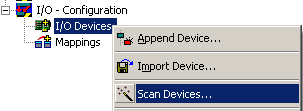
Automatic scanning in of the terminal
Based on an empty configuration, carry out an online scan to find the basic EtherCAT system and the Lightbus configuration.
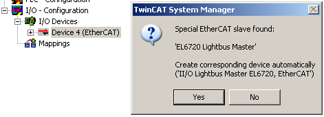
Once the EtherCAT system with its components, including the existing EL6720, has been created, the Lightbus system can be scanned.
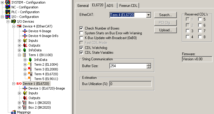
Then set the bus settings via the Lightbus device in the configuration. On startup they are downloaded to the EL6720.
Additional information regarding the EL6720 Lightbus implementation
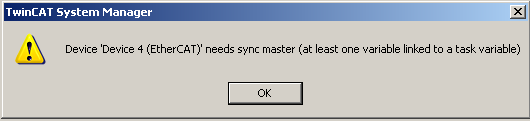
- As usual in TwinCAT, the Lightbus components require at least one link to a control task, otherwise is the bus is not triggered.
- If no link exists, TwinCAT issues the message "needs sync master (at least one variable linked to a task variable)".
- In contrast to the EtherCAT system, the Lightbus system only sends telegrams for process data that are linked.
Sample: A terminal has 4 digital inputs for BOOL variables, e.g. KL1004 or EL1004. In EtherCAT system a query with 4 bits would be sent to this terminal, regardless of whether and how many of the 4 inputs are actually linked with a task. In Lightbus system only 1 bit is used in the cyclic telegrams, if only 1 channel is linked from the terminal.
It follows that the circulating telegram length/data quantity/occupied CDL naturally depends on the topology, but also on the links. - The detailed display shows the used Lightbus capacity, i.e. how many data are currently sent in the selected cycle time.
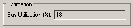
More detailed information for the individual CDLs can be displayed in the "own" CDL view.
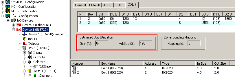
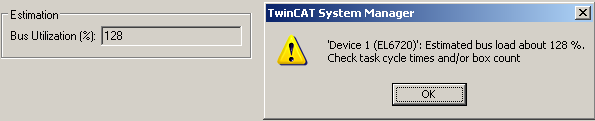
In this example the cycle time of 200 µs is too short relative to the (linked) process data, resulting in Lightbus overload.
A telegram can be assumed to be approx. 30 µs long.
The System Manager reports this on activation.
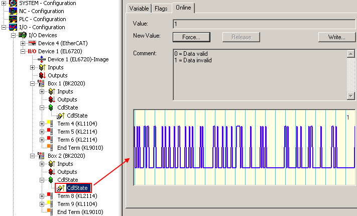
If such a system is then operated in Run mode, the lower-priority CDL cannot always be executed, and the diagnostic tool CdlState at times signals invalid input data with CdlState = 1.
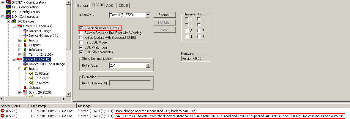
- The number of Lightbus devices (maximum 254) is checked routinely.
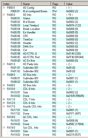
If the number of Couplers or Boxes is incorrect, the El6720 does not start in OP: "SAFEOP to OP failed". - The EL6720 has further diagnostic and configuration variables, which are shown in the CoE overview.
- Advanced Settings:
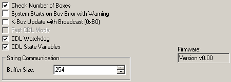
- Check Number of Boxes: see above
- System Starts ...: Without function
- K-Bus Update ...: Without function
- CDL watchdog
- CDL state variables: activates the CDL process data in the configuration tree
- Firmware display: in the EL6720 without function; the firmware version can be read in the CoE of the EL6720
- String communication: In the EL6720 the string communication of the FC20xx cards was changed to AoE and is therefore no longer relevant here.
Appending a terminal manually
The manual configuration setup is based on the steps described above.