Selective PDO mapping
Selective PDO mapping
Users can configure customized cyclic data exchange through selective PDO mapping. To this end a “full” set of process data is created on one side of the terminal. On the other side a subset of this set can now be defined for cyclic reading. This process is referred to as selective PDO mapping.
The default PDO assignment and mapping is removed, and the user has to create a custom PDO assignment and mapping. For this purpose, it is important to know the structure of a PDO assignment or mapping.
Basically (standard) there are two CoE objects 0x1C12 “Rx PDO Assign” and 0x1C13 “Tx PDO Assign”, in which the assignments for the data input (RxPDO) and the data output (TxPDO) for the secondary side and the primary side are defined. They contain a reference to CoE objects 0x1608 “IO RxPDO Map” and 0x1A08 “IO TxPDO Map”, in which the mapping the inputs and outputs is defined. All four of these CoE objects, 0x1C12/0x1C13 and 0x1608/0x1A08, have an RW flag (RW = read/write). The two mapping objects 0x1608 and 0x1A08 initially refer to the CoE objects 0x7000 “PD Outputs” and 0x6000 “PD Inputs” (process data inputs/ outputs), in which process data (structures) are stored. “Initial” refers to automatic configuration by TwinCAT, when the user adds new input or output data on the primary or secondary side. This can also be viewed in the [Startup] tab. This is where all the links for object references are created in the transition from PREOP to SAFEOP (P → S). The two “final” CoE objects 0x6000 and 0x7000 are “RO” (read only), since within the device the copy processes for input and output data are carried out in OP state.
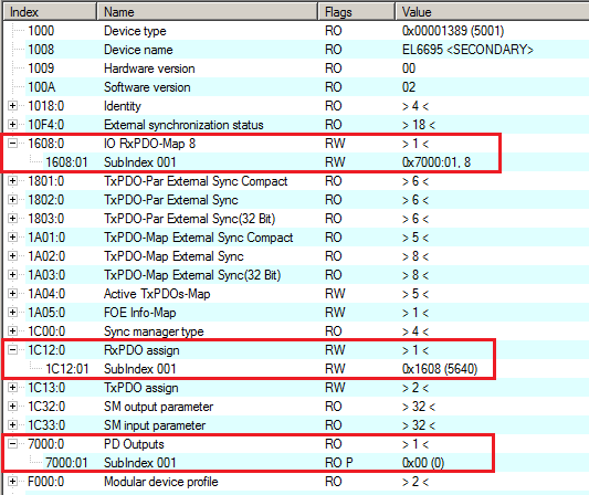 Fig.152: Basic mapping of a 1 byte variable via 0x1C12 to 0x7000 “PD Outputs”
Overview of the (initial) linked objects:
- RxPDO Assign: 0x1C12 → RxPDO Map 0x1608 → 0x7000 PD Outputs
- TxPDO Assign: 0x1C13 → TxPDO Map 0x1A08 → 0x6000 PD Inputs
 | Mapping of CoE objects 0x1608 points to 0x7000, and 0x1A08 points to 0x6000. The objects 0x7000 and 0x6000 are mirrored on the respective other side of the terminal. |
For example, if an object 0x7000:0E PD Outputs exists on the primary side, an object 0x6000:0E PD Inputs should be created on the secondary side for data exchange.
Procedure under TwinCAT
To create a selective mapping, the existing PDO configuration with its assignments should initially be disabled by unticking all options under outputs, inputs and downloads in the “Process Data” tab of the terminal.
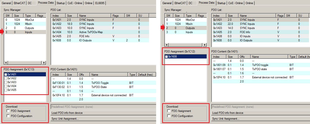 Fig.153: Process data in selective mapping
The existing entries in the Startup tab are then also deleted, and the terminal no longer has a process image. The process image is then redefined in two steps, as described below:
New entries have to be created in the Startup tab of the terminal. Select “New…” on the bottom right of this tab.
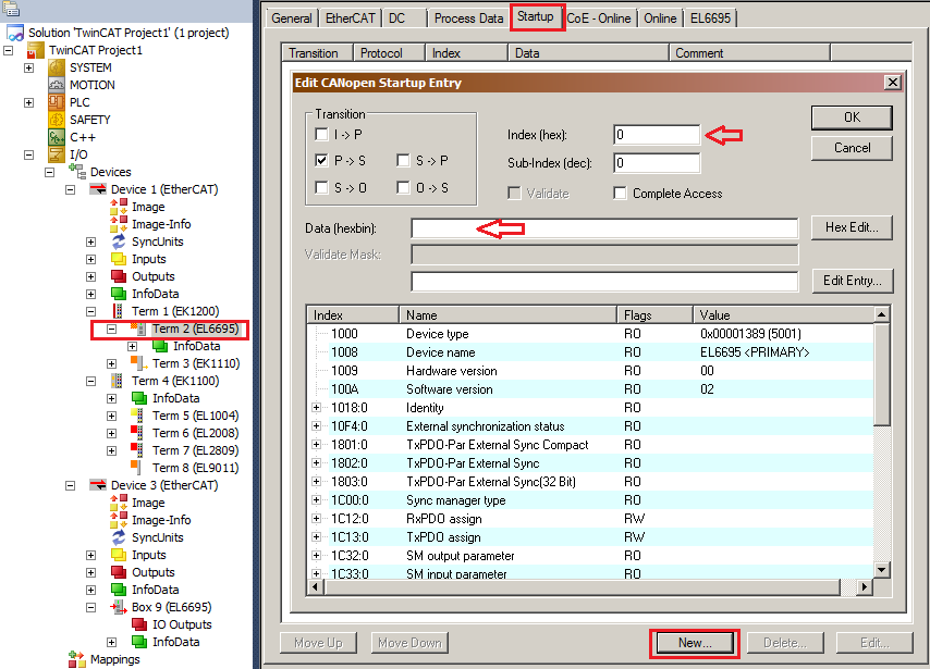 Fig.154: Creating new output variables (in this example: primary side of the EL6695)
As an example, a total of four output variables with sizes 8, 16, 32 and again 8 are created [recommended sequence]:
To this end a 0x1614 object (selectable from the range 0x1600 to 0x161F) is created in this example as follows (tick “Complete Access”; enter “IO RxPDO Map” as a comment, for example):
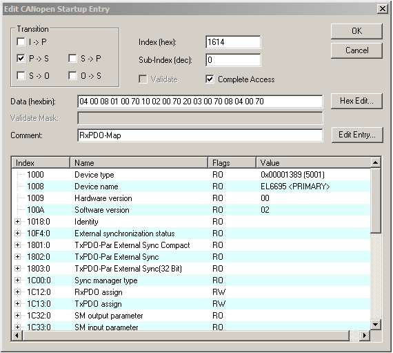 Fig.155: Setting up the 0x1614 object
- Enter: 04 00 08 01 00 70 10 02 00 70 20 03 00 70 08 04 00 70
Meaning of the entry data:
04 00 | Subindex number |
08 01 00 70 | Object 7000, index 1, length 8 |
10 02 00 70 | Object 7000, index 2, length 16 |
20 03 00 70 | Object 7000, index 3, length 32 |
08 04 00 70 | Object 7000, index 4, length 8 |
This can represent the data structure of a program object or structure, for example. In order to be able to link a structure variable with a PDO of the EL6695, it first has to be converted to a global data types under TC3:
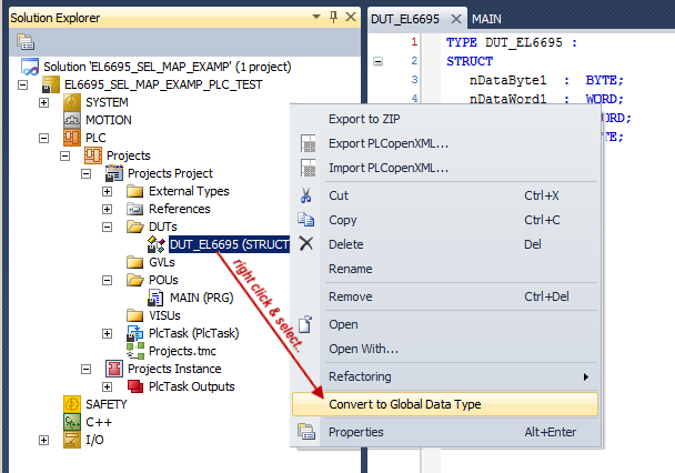 Fig.156: Conversion to a global data type
In the second step the following entries are made via the dialog “Edit CANopen Startup Entry”:
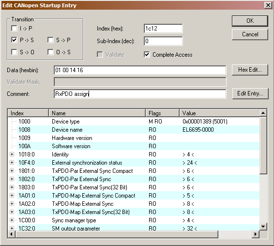 Fig.157: Creating object 0x1C12 for RxPDO
The CoE Startup entry to be created therefore is the index 0x1C12 with the subindex 0 (subindex for the start of the object). The tick at “Complete Acess” is set, so that the entered values are not interpreted as data type WORD, DWORD etc. The assignments should be made during the transition from PREOP to SAFEOP; only the tick “P → S” remains set (or is to be set) during the transition. Under “Comment” an explanatory comment can be added, which then appears in the CoE overview as the name of the object. The content of the CoE object is specified in “Data (hexbin)”.
The first two blocks define the number of subindices of the object (Hi/Lo byte switched: 01 00 → number of subindices = 1). This is followed by the content of the first subindex 01 with 14 16 → 0x1614.
- Enter: 01 00 14 16
This is now one of the references described above, in this case to the already created “RxPDO Map” object (0x1614).
The [Startup] tab should now look as follows:
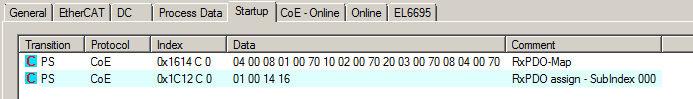 Fig.158: New PDO map and assignment objects on the primary side
It is important that “RxPDO assign” over object 0x1C12 is always at the end of the list of RxPDO Map entries. It may contain several references (as required). A data set would then look like this, for example: 06 00 03 16 1A 16 1E 16 08 16 04 16 .. etc.
Use the following steps to display the created variables in the configuration:
- Selection in the menu: [TwinCAT] → [Reload Devices]
- “Load PDO info from device” in the “Process Data” tab of the terminal
- Display the CoE online objects via “Update List”
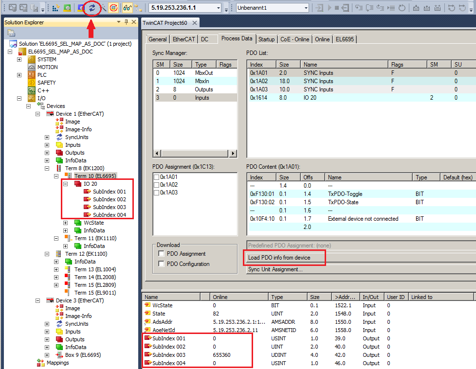 Fig.159: Newly created process data:object 0x1608
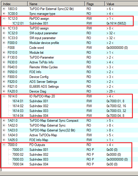 Fig.160: Display [CoE Online] the selectively created variables with the corresponding references
Creating the selective PDO variables
On the other side of the EL6695 bridge terminal, in this case the secondary side, selected “variables" can now be mirrored, if required. To this end, add the required variables in the “Solution Explorer”.
In this example, the primary side has a 1-2-4-1 byte structure, of which only the 2 byte and the 4 byte variable types ”WORD” and “DWORD” are to be provided as a subset of the whole process data, as shown:
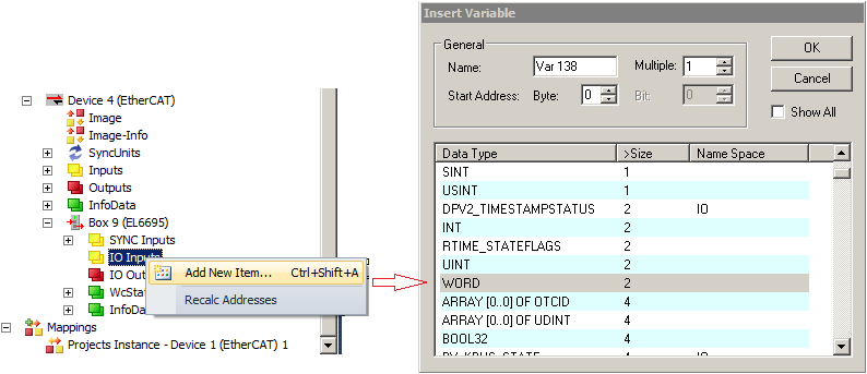 Fig.161: Adding selective PDO variables
The procedure for the DWORD variable is similar, as shown in the diagram.
Then complete the Startup entry as follows, to adapt the subindex values 02 for the WORD type and 03 for the DWORD type:
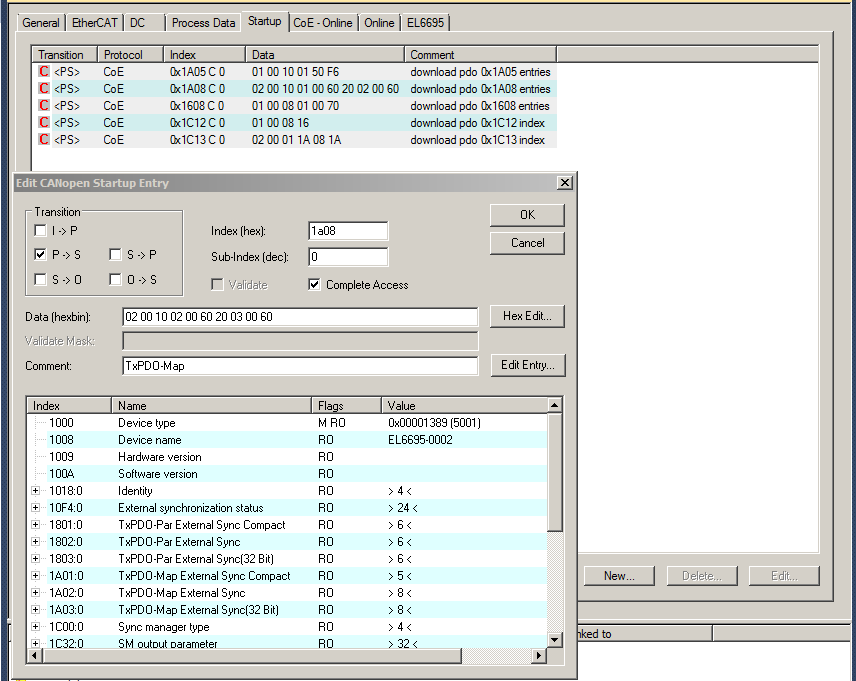 Fig.162: Startup entry 0x1A08 for overwriting (for correcting reference index 01 → 02 and 02 → 03)
- Enter: 02 00 10 02 00 60 20 03 00 60
Meaning of the entry data:
02 00 | Subindex number |
10 02 00 60 | Object 6000, index 2, length 16 |
20 03 00 60 | Object 6000, index 3, length 32 |
After a further “Reload” instruction and activation of the configuration, the selective PDO mapping is now available for use by the PLC programs. Note that, due to terminal-specific system characteristics, a special buffering mechanism is used for the real-time data exchange, so that the output variables always have to be configure with a byte at the start and a byte at the end (so called start/stop bytes). Links to PLC variables and therefore a data usage are not required for these “fillbyte” variables.
By an application of the EL6695 together with other EtherCAT masters the configuration procedure have to be adapted respectively.
Explanatory note regarding the use of start/stop bytes
For selective mapping in the output data, Beckhoff generally recommends to create a start byte at the start and a stop byte at the end. The technical reason lies in the internal memory management of the process data, where access to the last byte results in internal switching to the next EtherCAT buffer of the terminal; read access is then no longer available for this output package. If read access to the output buffer takes place selectively “from top to bottom”, this is not a problem. However, if the variables are read successively from different sections (which is probably the case in most applications) and the last byte is to be captured, the buffer is then locked, and no further data can be retrieved. An additional “empty” byte after the actual process data prevents inadvertent switching of the buffer.
The diagram illustrates that in many cases the start/stop byte wouldn't really be required:
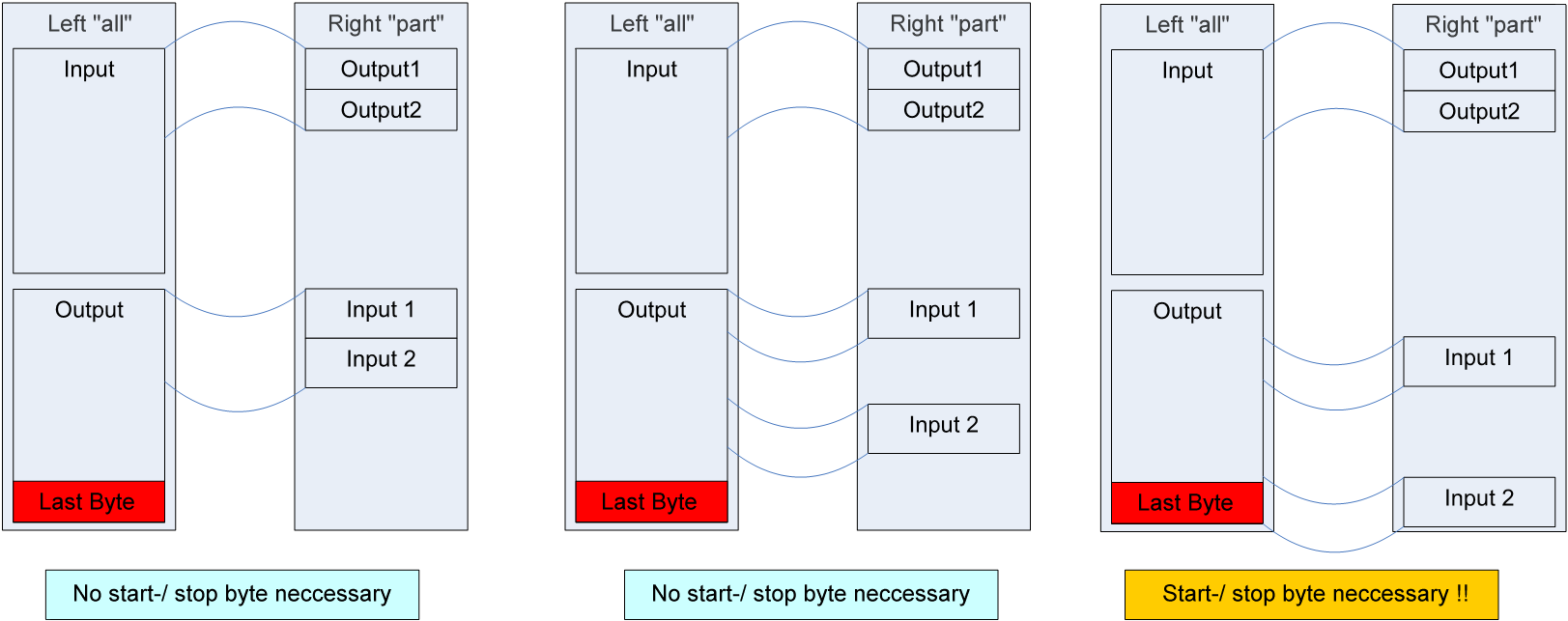 Fig.163: Using the start/stop byte
 | Inserting start and stop byte To avoid unexpected surprises during flexible utilization of the EL6695 over the service life of the application and any configuration changes, Beckhoff generally recommends to configure the output variables with a byte at the start and a byte at the end. |
| Using the sample programs This document contains sample applications of our products for certain areas of application. The application notes provided here are based on typical features of our products and only serve as examples. The notes contained in this document explicitly do not refer to specific applications. The customer is therefore responsible for assessing and deciding whether the product is suitable for a particular application. We accept no responsibility for the completeness and correctness of the source code contained in this document. We reserve the right to modify the content of this document at any time and accept no responsibility for errors and missing information. |