Internal and external EtherCAT synchronization
In a machine control with distributed components (I/O, drives, several masters) it may be useful for the components to operate with a close time link to each other. The components must therefore have a local “time”, to which the component (e.g. an I/O terminal) has access at all times.
Associated requirements may include:
- Several outputs in a control system have to be set simultaneously, irrespective of when the respective station receives the output data.
- Drives/axes in a control system must read their axis positions synchronized, irrespective of the topology or cycle time.
Both requirements necessitate a synchronization mechanism between the local times of the components of a control system. - If inputs affect the control system, the (absolute) time must be recorded. This can be helpful for subsequent analysis, if such an analysis is required for determining the sequence of events in functional chains.
This means that time running in the components must be coupled to a globally valid time, e.g. Greenwich world time or a network clock. - tasks on different controllers should run synchronous and without phase shift.
The terms “close temporal reference” or “simultaneous” can be interpreted depending on requirements: for a “simultaneity” in the 10 ms range a serial communication structure may be adequate, while in other ranges 100 ns or less are required.
 Fig.5: Simple I/O topology
 Fig. Simple I/O topology shows a simple EtherCAT topology consisting of a master, several I/Os and an axis. A local time is to be applied in different components. The tasks
- synchronization of local clocks
- coupling to a higher-level reference time
- task synchronization
are discussed below.
Requirement 1 + 2: synchronization
In an EtherCAT system the distributed clocks concept (DC) is used for synchronization of local clocks in the EtherCAT components. Further information can be found in the separate documentation.
Synchronization of local EtherCAT devices
General:
- 1 ns time resolution corresponds to 1 digit, scope of 64 bits corresponds to approx. 584 years
- The EtherCAT master must keep the distributed clocks synchronous within the system accuracy (EtherCAT: <100 ns) using synchronization datagrams.
- Not all EtherCAT devices have to support this feature. If a slave does not support this concept, the master will not include it in the synchronization. If the EtherCAT master does not support this feature, DC is also ineffective in all slaves.
- such a clock also runs in the EtherCAT master, in this case software-based.
- In the system one of the existing clocks is selected as reference clock and used for synchronizing all other clocks. This reference clock is usually one of the EtherCAT slave clocks, not the EtherCAT master clock. The clock of the first EtherCAT slave in the topology that supports distributed clocks is usually automatically selected as reference clock.
- A distinction is made between
- the EtherCAT master (the software that “manages” the EtherCAT slaves with Ethernet frames) and the EtherCAT slaves managed by it.
- the reference clock, which is usually located in the first DC slave, and the slave clocks whose time is based on it, including the clock in the EtherCAT master.
Master:
- During the system start phase the EtherCAT master must set the local time of the reference clock and the other slave clocks to the current time and subsequently minimize deviations between the clocks through cyclic synchronization datagrams.
- In the event of topology changes the EtherCAT master must re-synchronize the clocks accordingly.
- Not all EtherCAT masters support this procedure.
- The EtherCAT master in the Beckhoff TwinCAT automation suite fully supports distributed clocks.
Slave:
- Due to the high precision required this local clock is implemented in hardware (ASIC, FPGA).
- Distributed clocks are managed in the EtherCAT slave controller (ESC) in registers 0x0900 - 0x09FF. Specifically, the local synchronized time runs in the 8 byte from 0x0910.
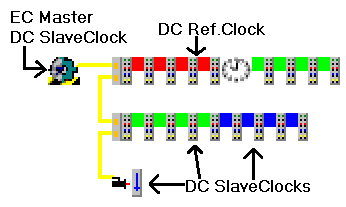 Fig.6: mapping of DC to the topology
In Fig. Mapping of DC to the topology the 3rd EtherCAT slave was selected as DC reference clock as a sample. The local time of this slave is now used to adjust all other distributed clocks, i.e. all other EtherCAT slaves and the clock of the EtherCAT master. This is achieved through synchronization datagrams, which the EtherCAT master sends cyclically.
This procedure ensures that all devices supporting DC always have local access to a time that is identical (within the DC synchronization precision) in all devices.
The system now operates based on the timebase of the selected DC reference clock and its local clock generator/quartz with TDC. Due to production tolerances this timebase is rarely the same as the official sidereal time/coordinated world time UTC TUTC or another reference time. This means that 1 msUTC is never exactly 1 msDC, TDC≠ TUTC. Over longer periods also drift processes may also change the ratio. As long as DC is used for relative processes within the EtherCAT system, the deviation from the UTC is irrelevant. However, if the DC time is to be used for data logging with a global timebase, for sample, the DC timebase must be synchronized with the UTC timebase. This is described in section Requirement 3.
Requirement 3: higher-level global time, absolute time
If the timebase TDC is to be adjusted based on a higher-level timebase, the timebase and the associated procedure must be selected. Generally common synchronization protocols are used for the synchronization. Samples for time sources and synchronization procedures are listed below.
- Sources: UTC world time, network time, adjacent control system, radio clocks (in Central Europe: DCF77)
- Procedures: GPS, radio clocks, NTP (NetworkTimeProtocol), SNTP (Simple NTP), PTP (IEEE1588), distributed clocks DC
The following synchronization precisions can be achieved (depending on the hardware)
- NTP/SNTP: ms range
- PTP: < 1 µs
- DC: < 100 ns
The following two control aims must be achieved:
- The frequency of the subordinate timebase must be adjusted to the higher-level timebase.
- Any offset between two absolute times does not have necessarily to be controlled to 0. It is sufficient for it to be announced and kept constant. The maximum offset adjustment is ±½ cycle time.
 | External EtherCAT synchronization External synchronization sources (e.g. EL6688, EL6692) can only be used from TwinCAT 2.11 used. In older versions of TwinCAT such EtherCAT slaves have no meaningful function. |
If a higher-level master clock is integrated in an EtherCAT system, a special EtherCAT device is generally used for the physical connection. The device monitors both timebases and is therefore able to determine the time difference.
Please refer to www.beckhoff.de for suitable products currently available for this purpose.
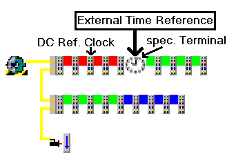 Fig.7: EtherCAT topology with external reference clock
The different timebases can be arranged hierarchically, so that at the start of the respective system the current absolute time is taken from the subordinate system. If necessary top-down synchronization is used, if external timebases or DC components are present in the system.
Readjustment of local time vs. higher-level absolute time
For the purpose of synchronization the local DC time is not adjusted based on the higher-level absolute time, but only to a constant offset. This offset is made available to the user as a process data. The offset is corrected by ±½ cycle time to ensure both tasks run in phase.
- When TwinCAT starts the EtherCAT master, the local DC system in the slaves is started and synchronized immediately.
- However, an external reference slave such as EL6688 (IEEE1588 PTP) takes a few seconds before it can supply a reference time that is synchronized with the higher-level clock.
- As soon as the external reference time is available, the offset to the local time is calculated and corrected by ±½ cycle time to ensure that both tasks run in phase, and the EtherCAT master Info Data are made available to the user for reconciliation with the local time values.
- From this time the offset is kept constant, depending on the selected control direction.
TwinCAT system behavior
External reference clock outage
If the external reference clock signal fails, both timebases will naturally drift apart again. Once the signal is available again, the system will once again be controlled based on the previous offset values.
TwinCAT can start without external clock signal. In this case the offset is calculated and maintained as described above, as soon as a stable external reference clock signal is received.
Settings in TwinCAT 2.11
External synchronization via EtherCAT is supported from TwinCAT 2.11. The synchronization direction can be set in the associated dialog.
Distributed clock timing settings
 Fig.8: TwinCAT 2.11 distributed clock settings - Sample for EL6688 in PTP slave mode as time reference for the local EtherCAT system
- Independent DC Time: one of the EL terminals (generally the first terminal supporting DC) is the reference clock to which all other DC terminals are adjusted. Selection of the reference clock in the dialog above.
- DC Time controlled by TwinCAT: the DC reference clock is adjusted to the local TwinCAT time.
- DC Time controlled by External Sync Device: if the EtherCAT system is to be adjusted to a higher-level clock, the external sync device can be selected here.
Process data settings
TwinCAT 2.11 can display the current offsets in [ns] in the EtherCAT master info data.
- These offsets are calculated once after EtherCAT has started.
- The synchronization control keeps these offsets constant.
- If local DC time values in the synchronized EtherCAT system are to be related to the absolute reference from the higher-level EtherCAT system (e.g. from EL1252 timestamp terminals), the user must adjust this offset with each local timestamp.
Sample: tEL1252 timestamp channel 1, absolute time = tEL1252 timestamp channel 1, local DC time + tExtToDcOffset
 Fig.9: display current offsets
 Fig.10: Current offsets