EL6652 EDS file
The following chapter is intended to explain to you, by way of an example, how an EDS file is interpreted and how you can use this information for the configuration of the slave in the System Manager.
The example uses an EDS file of the type Endress+Hauser: Promass 100 EDS

Selection of a connection
In the EDS file there are usually several connection options; in the yellow line you can see that the slave next to ‘connection 1’ requires 398 bytes of configuration data. Since the EL6652 does not support this, this connection cannot be used.
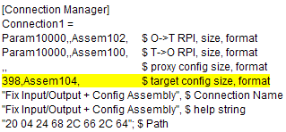 Fig.144: Connection" not to be used, communication data not equal to 0
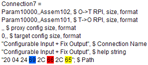
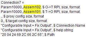
There are further connection options in the EDS, in this case Connection 7. The configuration data are set to "0" in this connection. This can be used for communication with the EL6652.
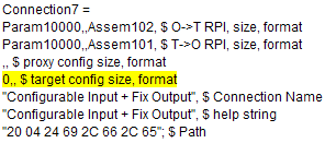 Fig.145: "Connection", communication data equal to 0
Another way of checking what the EL6652 supports is to include the EDS file in TwinCAT 3.1. There a connection can simply be added to an EtherNET/IP scanner and checked for the "Config Size". Normally the "Connection" options of an EDS file, which have a "Config Size" not equal to "0", are not offered as a selection option on an "Ethernet/IP Scanner (EL6652)".
The following pictures show the addition of "Connection" options of the same EDS file at the EL6652 and at the TwinCAT Function TF6281 as Ethernet/IP Scanner. It can be seen that more "Connection" options are selectable on the TF6281 than on the EL6652. This is due to the fact that these "Connection" options have a "Config Size" not equal to "0" and are therefore not supported by the EL6652.
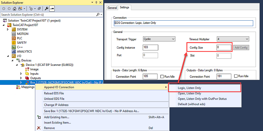 Fig.146: Connection" options equal to 0, EL6652
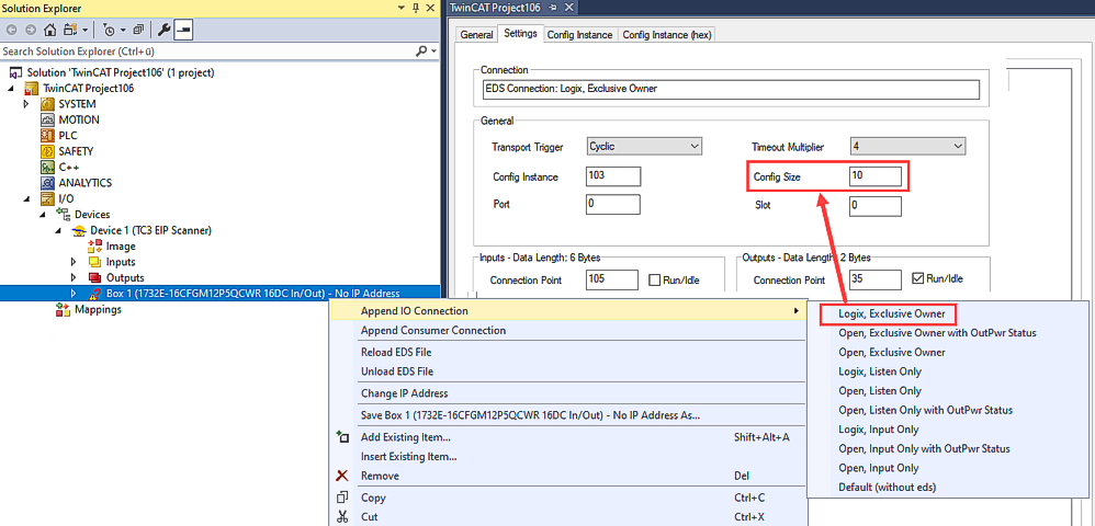 Fig.147: Connection" options not equal to 0, TwinCAT Function TF6281
Config, input and output instance
The config, input and output instances must now be read.
Blue corresponds to the config instance, red to the output instance and yellow to the input instance; these are usually represented in the EDS file as hex values and must be entered in the System Manager as decimal numbers.
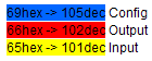
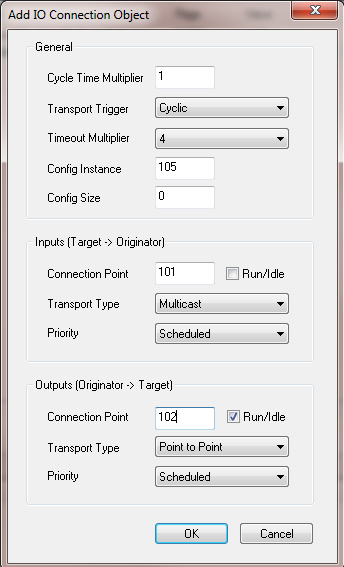 Fig.148: Enter the values in the "Add IO Connection Object" dialog box
Register the values according to the EDS file in the System Manager.
Cycle Time Multiplier
The EL6652 always operates internally with a cycle time of 1 millisecond. Some Ethernet/IP slaves are not designed for this time. The "Cycle Time Multiplier" can increase the time.
Check the EDS file to see which minimum value your slave can handle. If the slave is not able to process the cycle time of 1 ms, the time must be increased by a factor via the multiplier.
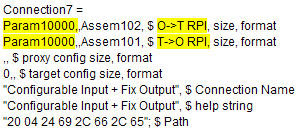
Theoretically, different RPI times can be used for the transmitting and receiving directions; however, the EL6652 always uses the same time for both directions. In this EDS file the parameters for the RPI are located in Param10000.
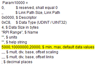
This Ethernet/IP slave can handle a minimum of 5 ms (5000 µs); the manufacturer specifies a default value of 20 ms. It is advisable to follow the manufacturer’s specification and to use the 20 ms. This means that a "Cycle Time Multiplier" of 20 is to be entered (1 ms * 20 = 20 ms).
Specifying the data length
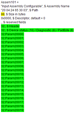
As the final step the data length must be entered; here again, the values are taken from the EDS file.
Assem102 corresponds to the output data, in the EDS file with 64 bytes; the green data correspond to the bits, in total 64 bytes again. These values can be taken in the System Manager as a basis in order to use the data just as they are represented in the EDS file. A byte array of 64 bytes can also be used, whose data are broken down in the PLC.
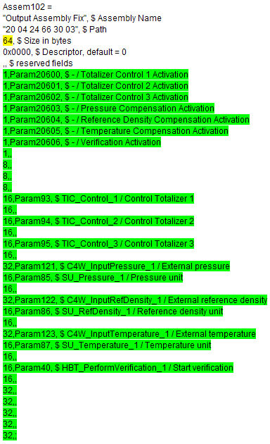
The output data in the System Manager are illustrated below; first of all 8 bits are inserted, then 3 x byte, 6 x INT, 1 x DWord, 2 x INT, etc., until the length corresponds to 64 bytes.
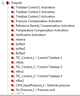 Fig.149: Output data in the System Manager
The inputs Assem101 are handled analogously:
On completion the configuration must look like the following:
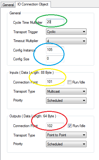 Fig.150: Configuration "IO Connection Object"
Summary:
Green: cycle time of the slave
Blue: config parameter (size always 0) config instance 105
Yellow: input instance Len 88 connection point 101
Red: output instance Len 64 connection point 102