Project planning of the PROFINET device
When establishing a PROFINET connection the controller always assigns an IP address to the device from its own address space (if the device does not yet have one or if it has a different one). In TwinCAT the next higher address is taken for a device by default (starting from the controller adaptor class); the subnet and gateway are the same as those of the controller. Before the actual assignment of the IP address to the device by the controller, an ARP is used to test for a possible address conflict or to check whether the device already has this IP address. If there is a conflict, e.g. that the IP address is already assigned in the network, the IO driver determines this and outputs a corresponding message in the logger window. If there is no reply to the ARP, this means that no device (the projected device included) is using this IP configuration, which in turn results in the controller assigning the IP settings to the device via a DCP_SET. Setting is skipped if it is determined via the ARP that the device sought already has the projected IP address.
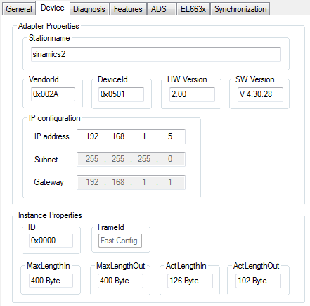
In addition the "InstanceID" and the "FrameID" can be changed in this window. However, the default settings are sufficient for most applications. The Instance ID is incorporated into the formation of the UUID object. A change should therefore be made only in exceptional cases. When changing the Frame ID the employed RTClass must be taken into account (e.g. for RTClass1 unicast 0xC000 - 0xFAFF). If the device is on an IRT controller and all devices have been switched automatically to RTClass3, the FrameID is managed automatically and there is no input option (marked by “Fast Config”).
In addition the current process data length can be checked in this menu, i.e. the MaxLengths indicate which process data size is supported by the respective device, while the ActLengths indicate the current process data length (incl. IOPS and IOCS). The corresponding error message appears if the maximum lengths are exceeded on appending further modules/submodules.
Various settings for the cycle time can be made on the “Features” tab. The controller cycle time for RTCLass1 must always correspond to a power of two, starting from 1 ms ( 1, 2, 4, 8…). If an incorrect base time has been selected, this is indicated by a corresponding message. For RTClass3 the 1 ms base time can be divided again and again by two (down to min. 31.25 µs). The device cycle time can be changed via the exponents. The minimum is always the Controller Cycle Time, unless a larger minimum cycle time than that of the controller is defined in the GSDML. The maximum for RTClass1 is 512 ms. The “SendClockFactor” is fixed here as the time base with the value 32 (31.25 µs * 32 = 1 ms). The “ReductionRatioFactor” is also referenced to this, i.e. an RRFactor of 4 means a cycle time of 4 ms. The transmission point can be shifted again within a cycle via the phase; i.e. where RR = 4 the phase can be 1 - 4. However, this value is only of importance in the case of a synchronized transmission.
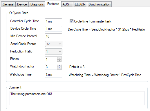
In addition there is an option here to adjust the PROFINET Watchdog factor, i.e. each device monitors the input of the cyclic data on the basis of this factor. If the factor is set to the default value (3) this means that, with an RR of 4, three cycles require 12 ms. Hence, a device reacts after 12 ms to missing telegrams (e.g. with an alarm and/or disconnection of the AR). The limits and values are recalculated each time when adjusting the individual factors.