Application sample - Flexible Ethernet Port
The application samples have been tested with a test configuration and are described accordingly.
Certain deviations when setting up actual applications are possible.
This sample illustrates the principle of remote access from a subordinate PC to the central EtherCAT controller via a flexibly connected EL6601 and EtherCAT.
The following elements were used:
- IPC with Windows XP SP2
- TwinCAT 2.11 b1534
- EL6601, SN xxxx0605
The approach
The task is to commission an extensive system with EtherCAT topology. To this end frequent access to the TwinCAT System Manager on the central PC is required. In practice the technician will primarily be at the local terminals/EtherCAT slaves during commissioning. The central System Manager as the TwinCAT target system should therefore be accessed from the respective coupler location via a remote PC and Ethernet.
Two mechanisms are used for this purpose:
- EtherCAT tunnels standard IP telegrams through dedicated slaves, e.g. EL6601, via the acyclic mailbox procedure
- Via the HotConnect functionality a coupler station (coupler + terminals) can be classified as freely pluggable in the configuration (.tsm). Special couplers must be used for this purpose.
A freely pluggable combination of EK1101 and EL6601 (HotConnect group) can now be used as a flexible Ethernet interface.
Possible configuration
A possible configuration is described below:
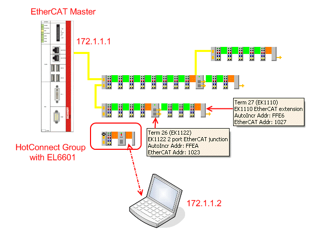 Fig.176: Structure HotConnect Group
The system offers EK1110 (end couplers), EK1122 (junction terminals) and free EK1100 ports for connecting the HotConnect group. The IP addresses should be regarded as samples, the notes from the previous samples must be taken into account.
No further settings are required at the TwinCAT/EtherCAT master. EoE is automatically forwarded in TwinCAT 2.11.
 | Remote access operability and EtherCAT state The process of Ethernet pass-through described here only works as long as the EtherCAT master and the EL66xx are at least in state PREOP. Otherwise no mailbox traffic and therefore no Ethernet transport takes place. However, if the network structure is already functional, this does not represent an insurmountable obstacle for general commissioning. |
| Change of location and EtherCAT state Once the HotConnect group is reconnected with the EtherCAT network it may take several seconds for the group to participate in the data traffic again, the EL66xx to be in OP state again and the link (see link LED) to be restored. |
Sample configuration
A small EtherCAT system is commissioned, the offline topology view in the System Manager shows two coupler stations and one non-localized station with an EK1101.
- In offline state the System Manager does not know where the EK1101 station with its ID was connected.
- The current assignment is visible online, the EK1101 with the EL6601 is connected to the second port of the EK1100.
- All slaves are in OP state, so that this system can now be accessed as target system from the remote PC.
- In the remote system an empty System Manager is opened and the EtherCAT computer with the IP 172.1.1.1 (in this sample) is located as the target system via IP
(Tab Actions -> Choose Target System -> "Search (Ethernet)" -> [enter IP 172.1.1.1] -> "Enter Host Name / IP") - After double-clicking on the line showing the found target system the user can log into the target system:
- After successful connection the configuration can be loaded by the target system through "Open from target system".
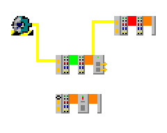 Fig.177: EK1101 localized with EL6601
 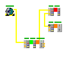 Fig.178: EK1101 localized with EL6601
 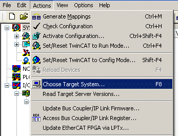 Fig.179: Selection of the target system
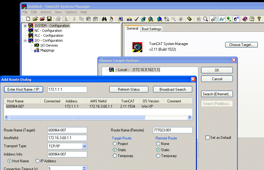 Fig.180: Enter target system 172.1.1.1
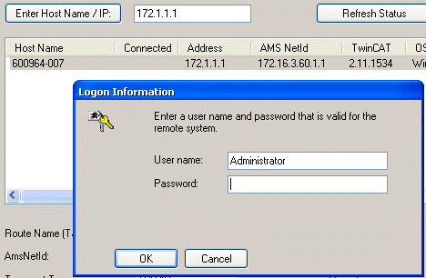 Fig.181: Entry of logon information on target system
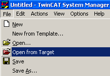 Fig.182: Opening of target system and loading of configuration
Checklist
The following checklist can be used for a successful configuration up to remote access:
- Successful EtherCAT configuration
- no LostFrames
- EtherCAT master and all slaves in OP state
- all WorkingCounters = 0; if necessary, set up special SyncUnits for deliberately inactive slaves - Set a different IP address for the EtherCAT port and the port used at the laptop, but within the same subnet section.
(here: 172.1.1.1 and 172.1.1.2) - Check the connection from both sides through ping commands
- Establish connection as target system
| Ethernet connection It is advisable to use credible addresses in the Properties dialog of the network interface, IP protocol (Windows XP SP2) Default gateway and DNS server, although they are not actually required. Settings of the remote PC from the sample: |
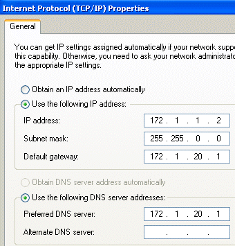 Fig.183: Entry of network addresses in the remote system