Quickstart
No special measures are required for the initial commissioning of the EL6201.
Knowledge of the introductory Technology section is required.
The following examples initially illustrate manual addressing and integration of a digital AS-i slave in the TwinCAT system.
For automatic addressing the EL6201 is commissioned with two digital and one analog AS-i slave, for example.
The EL6201 is commissioned with the following configuration:
- Operating system Windows 7 Professional SP1
- TwinCAT 2.11 R3 Build 2256, AS-i System Manager Extension installed
- Terminal network EK1100, EL1202, EL6201 and EL9010
- AS-i standard power supply unit 30.5 V
- AS-i slave 2 button / 2 LED
- AS-i slave 4 digital inputs
- AS-i slave 4 digital outputs
 | AS-i System Manager extension for 32-bit and 64-bit Windows systems The AS-i System Manager extension has been tested and runs under 32-bit and 64-bit Windows 7 Professional SP1. |
1. Mounting and connection
 WARNING
Bring the Bus Terminal system and the AS-i power supply unit into a safe, de-energized state before starting installation, disassembly or wiring of the Bus Terminals!
- Mount the EL6201 in the terminal network as described in the section Mounting and wiring.
Cable lengths
When using the EL9520 (potential distribution terminal with filter, AS-i power 24), the maximum expansion of the network topology may not exceed 50 m!
When determining the total length, all branches should be included (Fig. Wiring diagram for connecting the AS-i power supply unit and AS-i slaves with the EL6201).
If an AS-i standard power supply unit is used, the maximum topology expansion is 100 m.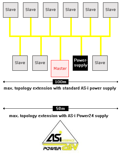
Maximum topology extent with standard AS-i power supply and AS-i Power24 supply - Connect the AS-i slave and the standard 24 V power supply unit to the EL6201 according to the following wiring diagram (Fig. Wiring diagram for connecting the AS-i power supply unit and AS-i slaves with the EL6201). Correct connection of the slave as described in the Technology section is required.
- Alternatively the AS-i slaves can be supplied with power via the EL9520 AS-i potential supply terminal as described in the Connection section.
Wiring diagram AS-i slave / EL6201 - Switch the Bus Terminal system power supply and the AS-i power supply unit on.
2. Configuration
Creating a TwinCAT configuration
| New features from firmware 02 and TwinCAT plug-in, version 2.1 Firmware 02: |
| Download the latest EtherCAT XML Device Description and the AS-i System Manager Extension Make sure that you download the latest XML file from the download section on the Beckhoff website and install it in accordance with the installation instructions. |
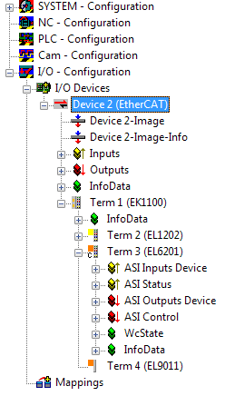
- Create a configuration in the TwinCAT System Manager by manually inserting the terminal or scanning it online. Refer to installation chapter TwinCAT 2.x regarding this.
- The TwinCAT tree now looks like this:
Manual addressing of the AS-i slave
| AS-i address The address of a brand new AS-i slave is always "0". |
The addressing of a brand new AS-i slave can be done using the TwinCAT System Manager. The installation of the AS-i System Manager Extension is required for this.
- Click on the EL6201 in the TwinCAT tree (A) and the “Settings” tab (B). Then click on "AS-i System Overview" (C) to navigate to the AS-i overview below, which shows the AS-i slaves to be addressed.
- The "AS-i Config Mode" (D) field in the status bar is shown in blue. If a green field “ASI Protected Mode” is displayed here, click on the field to access the “ASI Config Mode”
Status Bar
The status bar in the system overview indicates the system state. Underlined settings can be changed (switch between config mode/protected mode, activation/deactivation of data exchange).
- The slave “0” (E) marked with the yellow dot is the connected slave that has already been detected and which is to be given a valid address
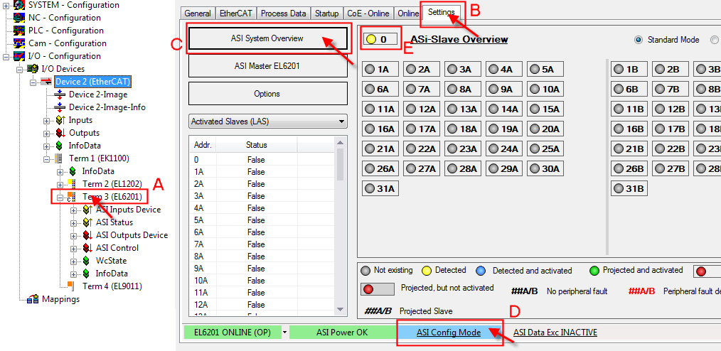
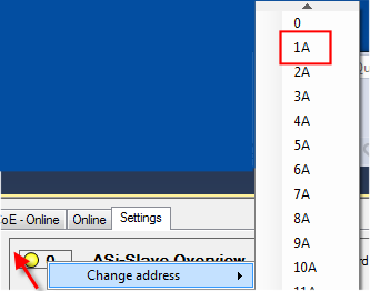
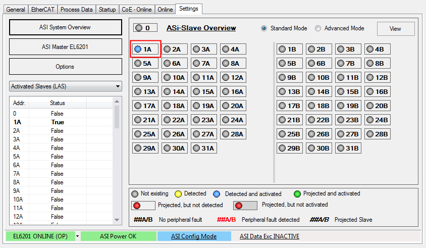
AS-i system overview with the slaves to be addressed - In order to convert the slave address "0" into a valid address, right-click on the yellow dot in the address field "0" so that you can then select an AS-i address via the "Change Address" selection field; for instance the address "1A" in the example.
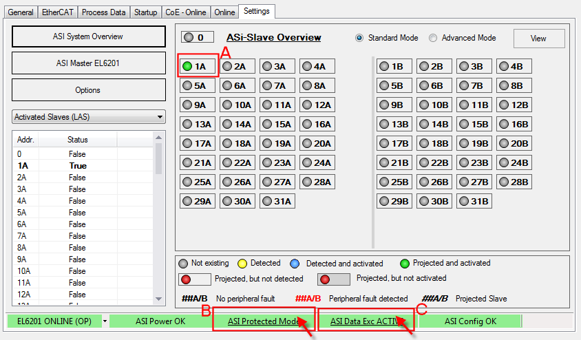
Address assignment for the AS-i slave - The address is now shown as "Detected and activated" (blue).

Address assignment for the AS-i slave accepted - In order to conclude the projecting for the slave, click on the blue field "ASI Config Mode" (B); the system switches to "ASI Protected Mode" (green field).
- In order to enable the AS-i data exchange, click on the grey field "ASI Data Exc INACTIVE"; the field changes to green "ASI Data Exc ACTIVE" (C).
- The completed configuration is indicated by the green field “ASI Config OK”.
Automatic addressing of the AS-i slaves
| AS-i-address for automatic addressing For automatic allocation of AS-i addresses in the EL6201, the connected AS-i slaves must have the address "0" (not addressed). |
Automatic addressing is also done via the AS-i System Manager extension.
- The AS-i slaves referred to above are not yet connected to the AS-i fieldbus line and have the address "0" or come straight from the factory.
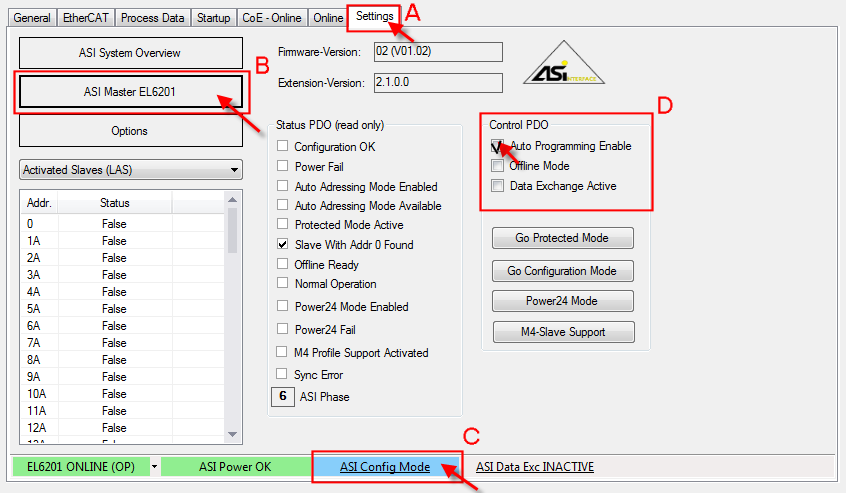
- Click on the EL6201 in the TwinCAT tree and the "Settings" tab (A). Then click on "AS-i master EL6201" (B) to open the screen shown below.
- Ensure that the terminal is in "ASI Config Mode" (blue). If necessary, change the mode by clicking (C).
- Set "Auto Programming Mode" in the field "Control PDO" (D).
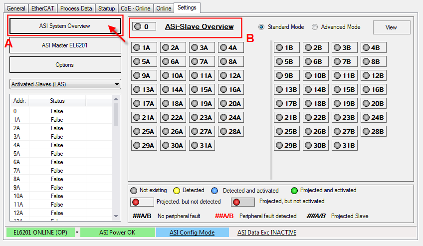
Activating "Auto Programming Mode" - Now click on "AS-i system Overview" (A), as shown in Fig. Switching to "Protected mode" and completion of project planning. As you can see in the image below, no slave is detected/projected (B).
No slave detected in the AS-i System Overview - Now connect the first slave with the AS-i fieldbus line. The slave is automatically addressed with "1A", as shown below (Fig. The first slave connected is allocated address "1A"). The address is now permanently implemented in the slave.
- Now connect further slaves with the AS-i fieldbus line. The slaves are allocated addresses "2A" and "3A", as shown below.
The first slave connected is allocated address "1A" 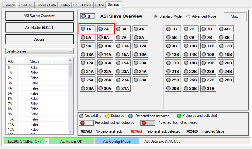
The second slave connected is allocated address "2A" Problems during project planning through AS-i "Periphery Fault"
During project planning of a new AS-i slave, an AS-i "Periphery Fault" may put automatic project planning into an undefined state, as indicated by flashing in the project planning overview; see Fig. Undefined state of a slave to be projected.
Remedy:
Click on the grey button "AS-i Data Exc INACTIVE", which switches to green "AS-i Data Exc ACTIVE" (see Fig.). The slaves should then show a stable state "Detected and activated" (blue).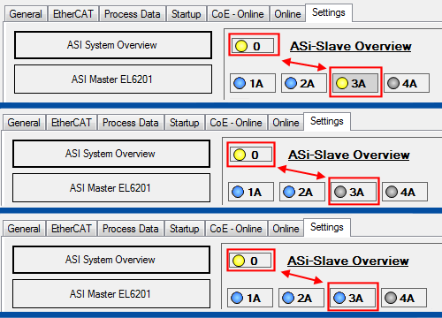
Undefined state of the slave to be projected 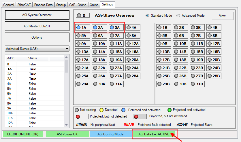
Remedy: Activating AS-i data exchange 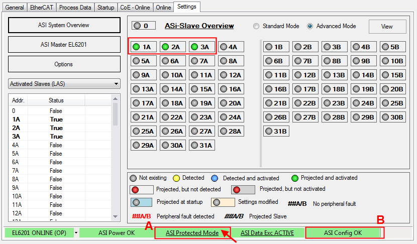
The third connected slave is allocated address "3A"; switching to "AS-i Protected Mode"; confirming the configuration - Now click on the blue "AS-i Config mode" button to complete the project planning (Fig. The third contacted slave is allocated the address "3A"; switching to "AS-i Protected mode"; confirming the configuration). The green "ASI Protected Mode" button appears (A). Confirm correct project planning with "ASI Config OK" (B).
Failure of a slave in the AS-i configuration
| Automatic addressing if a slave is replaced A faulty slave can be replaced with a brand-new slave or with a slave addressed with "0". |
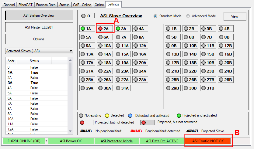
In the event of a fault (interruption of the connection between the slave and the AS-i fieldbus), the affected slave is shown as "Projected, but not detected" (A) - see Fig. Failure of slave "2A". The green "AS-i Config OK" light goes out and switches to a red "AS-i Config NOT OK" (B)
Remedy: Check the connection between the slave and the AS-i fieldbus line. A screw-connection of the slave used in this example may be inadequate, so that the required penetration depth to the fieldbus cable is not achieved.
Changes in the AS-i slave overview
The choices available for "ASI System Overview" display are shown in the screens below:
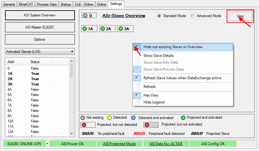
In order to only show the slaves, which are currently projected and active, right-click in the grey area below the slaves (or select the menu via the button "View") and select "Hide non-existing slaves in overview" in the context menu (Fig. Displaying the detected and currently projected slaves without details)
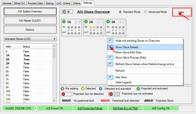
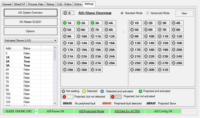
In order to show the details of the slaves, which are currently projected and active, right-click in the grey area below the slaves (or select the menu via the button "View") and select "Show slave details" in the context menu (Fig. Detected and projected slaves shown with details)
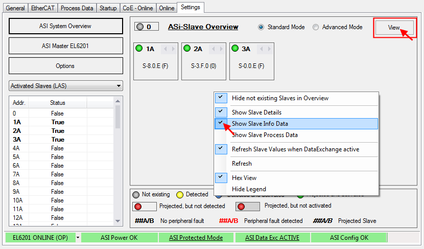
You can now choose between "Show Slave Info Data" and "Show Process Data" (see Fig. above)
3. Setting the parameters and process data
CoE parameters
If the default CoE parameters are to be changed, they must be saved for each channel in the CoE.
| Parameterization via the CoE list (CAN over EtherCAT) The terminal is parameterized via the CoE - Online tab (double-click on the respective object) or via the Process Data tab (allocation of PDOs). |
The CoE settings can also be loaded via the SPS/PLC/Task at runtime.
4. Operation
If voltage/current is present, the process data will now be exchanged, e.g. in the TwinCAT FreeRun mode, following a TwinCAT restart.