LEDs and connection
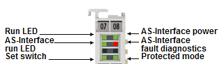
LEDs
|
LED |
Color |
Meaning | |
|---|---|---|---|
|
RUN |
green |
These LEDs indicate the terminal's operating state: | |
|
off |
State of the EtherCAT State Machine: INIT = initialization of the terminal | ||
|
flashing |
State of the EtherCAT State Machine: PREOP = function for mailbox communication and different standard-settings set | ||
|
Single flash |
State of the EtherCAT State Machine: SAFEOP = verification of the Sync Manager channels and the distributed clocks. | ||
|
on |
State of the EtherCAT State Machine: OP = normal operating state; mailbox and process data communication is possible | ||
|
flickering |
State of the EtherCAT State Machine: BOOTSTRAP = function for terminal firmware updates | ||
|
AS-i Diag |
green |
This LED lights up during the AS-i data exchange phase (it flickers in regular operation). | |
|
Set switch |
green |
This LED is on as long as both set inputs are short-circuited. | |
|
AS-i Power |
green |
This LED is on as long as the AS-i power supply is connected and at least one AS-i slave was found. | |
|
AS-i fault diagnostics |
red |
This LED flashes if the nominal and actual configuration do not match.
| |
|
Protected mode |
green |
This LED lights up as long as the two protected mode inputs are short-circuited. | |
AS-i installation
 WARNING
Bring the Bus Terminals system into a safe, de-energized state before starting mounting, disassembly or wiring of the Bus Terminals.
Connection of the AS interface
|
Terminal contact |
Name |
Use |
|---|---|---|
|
1 and 5 |
SCM |
Setting of the configuration mode by briefly bridging contacts 1 and 5 |
|
2 and 6 |
ASi+ |
ASi+ connection (brown). Both terminal points identified with ASi+ are connected internally. |
|
3 and 7 |
ASi- |
ASi- connection (blue). Both terminal points identified with ASi- are connected internally. |
|
4 and 8 |
SPM |
The detected slaves from the list of detected slaves can be projected for the protected mode by briefly bridging the two SPM contacts 4 and 8. |
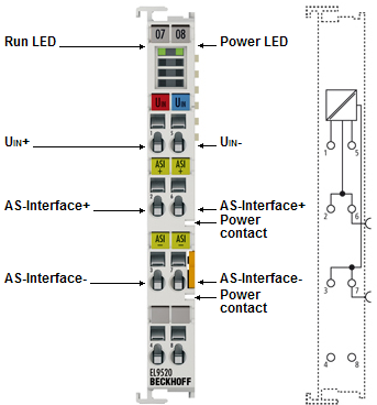
Connection AS-i potential supply terminal EL9520
|
Terminal contact |
Name |
Use |
|---|---|---|
|
1 |
Uin+ |
Positive voltage input 24 V..35 V |
|
2 |
ASi+ |
Connection AS-i+ |
|
3 |
ASi- |
Connection AS-i- |
|
4 |
|
not used |
|
5 |
Uin- |
Negative voltage input 24 V..35 V |
|
6 |
ASi+ |
Connection AS-i+ |
|
7 |
ASi- |
Connection AS-i- |
|
8 |
|
not used |
Wiring of the AS interface
Since the user data are modulated on the power supply line with the AS-Interface, a special AS-i power supply unit (30.5 VDC) is required.
A further possibility is offered by the EL9520 AS-i potential supply terminal, which provides the supply direct from the EtherCAT Terminal network.