Basic function principles
In principle the EL6090 has two product properties: the EL6090 as a display and/or as a counter or chronometer. They can be used in combination.
The EL6090 as a display
Texts can be shown in the terminal and therefore on the display. These texts are transferred to the terminal via CoE. Via the process data the NAVI switch can be read and thus new texts or variables modified in the PLC. The NAVI switch has five positions, which are all shown as BIT in the process data. Alternatively a placeholder can be used for the display text, which can than display an INT variable that is sent via the output process data. One INT variable (DIS output) is available for each row for this purpose; i.e. 2 INT values, each for one row. A further placeholder can be used for the EtherCAT status or the operating hours counter (see example)
The EL6090 for use as a counter, time measurement and operating hours counter
The operating hours counter can be regarded as being similar to the milometer of a car. It starts counting as soon as the terminal is live and cannot be reset. In addition the terminal has four time counters. Unlike the operating hours counter, these can be controlled and reset.
The four timers operate independent of each other. The counter is started with a start bit. It runs until the flag is set to "zero" again. A further flag can be used to reset the clock to zero. This feature can be used, for example, to determine how long a machine has been in productive operation. A further timer can be used for monitoring downtimes, a third for logging the time the machine is in an error state. The times are saved every 15 minutes, so that the values are retained when the machine is switched off. The chronometers stop if the terminal exits from the OP status.
In addition the EL6090 has four counters that are incremented by 1 in the event of a positive edge of the output data word. This can be used for quantity recording, for example (i.e. how many parts were produced, how many failed the test, etc.).
Like the counter, the chronometer is saved automatically every 15 minutes. If the machine is shut down in a controlled manner, data saving can also be triggered manually, in order to enhance the accuracy of the counters and chronometers.
The chronometer and counter values are 4-byte variables, i.e. at 1 second per digit an overflow would occur after 139 years, for the counters after approx. 4.29 billion.
Configuration
 | EtherCAT XML device description and configuration files We recommend downloading the latest EtherCAT Device description from the download area on the Beckhoff website and installing it according to the installation instructions. |
The process image is freely configurable. In this way it is possible to reduce the process data for internal application to a minimum.
INPUTS:
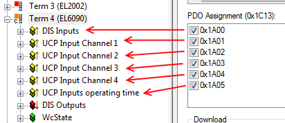 Fig.124: Assignment of the inputs to the PDOs
0x1A00 - for the NAVI switch
0x1A01 - for counter 1 and timer 1
0x1A02 - for counter 2 and timer 2
0x1A03 - for counter 3 and timer 3
0x1A04 - for counter 4 and timer 4
0x1A05 - for the operating hours counter
OUTPUTS:
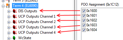 Fig.125: Assignment of the outputs to the PDOs
0x1600 - INT variables for the placeholder in the display
0x1601 - start/reset counter 1 and start/reset timer 1
0x1602 - start/reset counter 2 and start/reset timer 2
0x1603 - start/reset counter 3 and start/reset timer 3
0x1604 - start/reset counter 4 and start/reset timer 4
PDO 0x1A00 is used for actuating the NAVI switch via the process data.
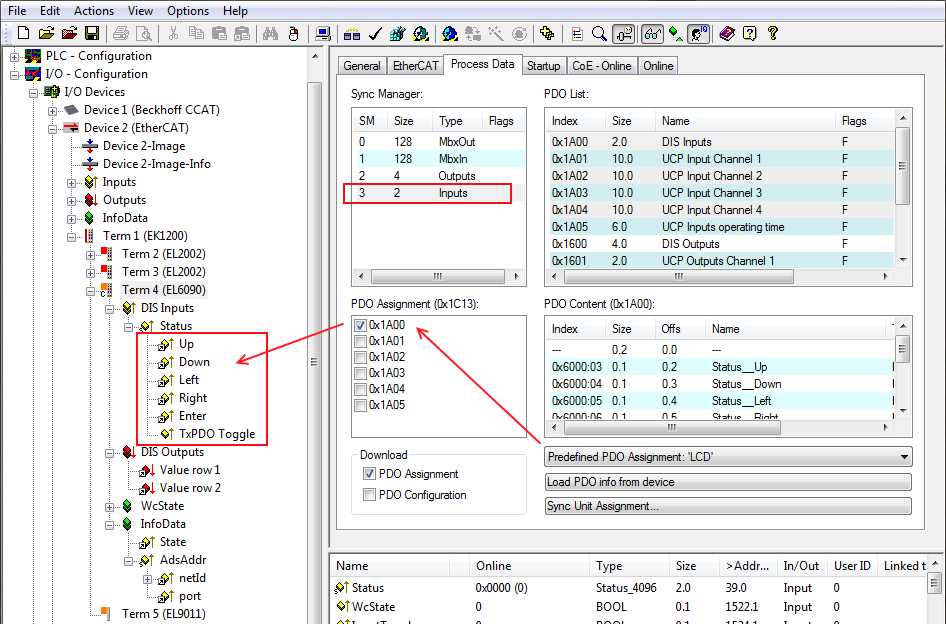 Fig.126: PDO 0x1A00 (predefined PDO assignment ‘LCD’) for actuating the NAVI switch
PDO 0x1600 is used for displaying the placeholder for INT variables.
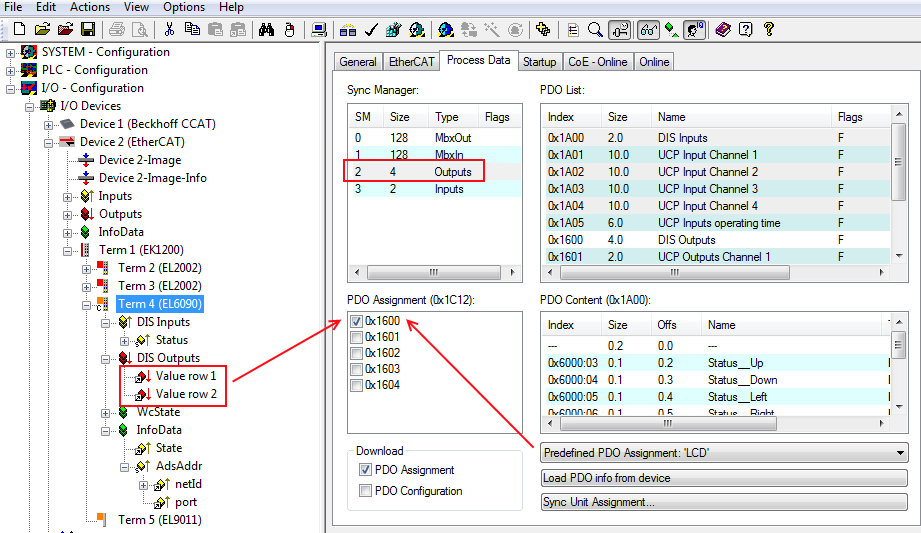 Fig.127: PDO 0x1600 (predefined PDO assignment ‘LCD‘) for displaying the placeholders for INT variables