LEDs and connector assignments
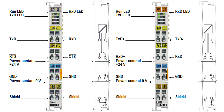 Fig.29: EL6001, EL6021-00xx - LEDs and connector assignments
LEDs
LED | Color | Meaning | |
|---|---|---|---|
RUN | Green | This LED indicates the terminal's operating state: | |
Off | State of the EtherCAT State Machine: INIT = initialization of the terminal or BOOTSTRAP = function for firmware updates of the terminal | ||
flashing | State of the EtherCAT state machine: PREOP = function for mailbox communication and variant standard settings | ||
Single flash | State of the EtherCAT state machine: SAFEOP = verification of the Sync Manager channels and the distributed clocks. | ||
On | State of the EtherCAT State Machine: OP = normal operating state; mailbox and process data communication is possible | ||
TxD | Green | State of the transmit signal line (on: HI signal level on transmit line) | |
RxD | Green | State of the receive signal line (on: HI signal level on receive line) | |
EL6001 terminal connector assignments
Terminal point | Name | Direction | Signal |
|---|---|---|---|
1 | TxD |
| Signal line (Transmit Data) |
5 | RxD |
| Signal line (Receive Data) |
2 | RTS |
| Control line (Request To Send) |
6 | CTS |
| Control line (Clear To Send) |
3 | GND | - | Ground (internally bridged with terminal 7) |
7 | GND | - | Ground (internally bridged with terminal 3) |
4 | Shield | - | Shield (internally bridged with terminal 8) |
8 | Shield | - | Shield (internally bridged with terminal 4) |


EL6021-00xx terminal connector assignments
Terminal point | Name | Direction | Signal |
|---|---|---|---|
1 | TxD+ |
| Signal line + (Transmit Data) |
5 | TxD- |
| Signal line - (Transmit Data) |
2 | RxD+ |
| Signal line + (Receive Data) |
6 | RxD- |
| Signal line - (Receive Data) |
3 | GND | - | Ground (internally bridged with terminal 7) |
7 | GND | - | Ground (internally bridged with terminal 3) |
4 | Shield | - | Shield (internally bridged with terminal 8) |
8 | Shield | - | Shield (internally bridged with terminal 4) |
Connection for RS422 transfer
In RS422 mode, data can be transferred in full duplex mode.
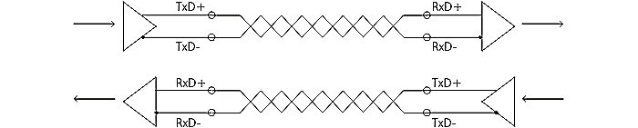 Fig.30: Connection for RS422 transfer
One receiver is recommended for RS422, but up to 10 receivers are common. The more complex the network becomes (subscribers, branches, plug connections), the more complex the commissioning becomes, because the appropriate parameters must be determined for reliable communication: Termination (where and at what height), baud rate, line lengths if necessary.
A clear line topology with short branches (MultiDrop) is strongly recommended, if necessary terminated at both end points with the greatest distance.
Connection for RS485 transfer
In the RS485 operating mode, the data is exchanged in half-duplex transmission. In this operating mode, a bus structure consisting of several stations communicating with each other can be set up.
A clear line structure with short branches is recommended.
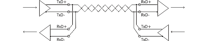 Fig.31: Connection for RS485 transfer
The transmit and receive lines are connected to one another in RS485 operating mode. As a result, the terminal receives not only the data from other devices, but also its own transmitted data. This can be suppressed with the index 0x8000:06 “Enable half duplex” in the Settings object.
In operating mode RS485, the reception of new data is only possible if transmission is complete.
“Enable half duplex” | “Enable point to point connection (RS422)” | Mode |
|---|---|---|
0 | 0 | RS485: |
0 | 1 | RS422: |
1 | 0 | RS485: |
1 | 1 | RS422: |