Product description
Technology
The EL600x and EL602x serial interface terminals enable the connection of devices with an RS232 (or RS485 / RS422) interface. In the case of the EL600x, the data is exchanged with the controller in full duplex mode; in the case of the EL602x, half duplex mode is additionally possible. The terminal has one receive buffer an one transmit buffer per channel, see technical data. Data transfer between the terminal and the controller takes place via a handshake.
The factory setting of the terminals is:
- 9600 baud
- 8N1: 8 data bits, 1 stop bit, no parity
- in the EL600x the RTS/CTS control is active
- the EL602x operates in full duplex mode with deactivated point-to-point connection.
Basic principles
During transfer of several bytes of data, the data (x bytes or 8*x bits in total) are sent in individual telegrams containing 7 or 8 bits, based on the coding specification (e.g. 7E2 or 8N1). A telegram consists of:
- Start bit
- Data bits (7 or 8, starting with the LSB [least significant bit])
- Optional: parity bit
- "E" EVEN: The parity bit is set by the sender such that the parity is even
- "O" ODD: The parity bit is set by the sender such that the parity is odd
- "N" NOT: no parity bit
- "M" MARK: The parity bit is set to 1 by the sender
- "S" SPACE: The parity bit is set to 0 by the sender
- Stop bit (1 or 2)
Accordingly, the coding specification 8N1 means: 8 data bits, no parity bit, 1 stop bit.
If 7-bit coding is selected, of each data byte that is transferred from the PLC to the terminal via the cyclic process data, only the lower 7 bits are sent. In other words, if 10 bytes of data (consisting of 8 bits) are sent to the EL60xx, 10 telegrams of 7 bits each are sent.
If 9-bit coding is selected, the 16-bit process data interface must be used. The terminal then expects the 9 useful bits in the lower 9 bits of the 16-bit word.
Frequency
The frequency of the data transfer must be known in the sender and receiver and match within a few percent, in order to ensure that the receiver can correctly detect any changes in level on the line.
Handshake
An additional handshake between the sender and the receiver can be used so that the receiver can indicate that it is ready to receive. The EL60xx supports two types of handshake:
- via special RTS/CTS data cables
- This features must be activated in the CoE.
- Only possible with EL6001/EL6002.
- via special data telegrams
- This features must be activated in the CoE.
RS Standards
The term RS232 (RS-232) is used in this document briefly for the ANSI/EIA/TIA-232-F standard.
The term RS422 (RS-422) is used briefly in this document for the ITU-T V.11 standard according to ANSI/TIA/EIA-422-B-1994.
The term RS485 (RS-485) is used in this document briefly for the ANSI/TIA/EIA-485-A-98 standard.
Level interfaces
The EL6001/6002 devices operate at an RS232 level with reference to GND, the EL6021/6022 devices with a differential RS485/422 level.
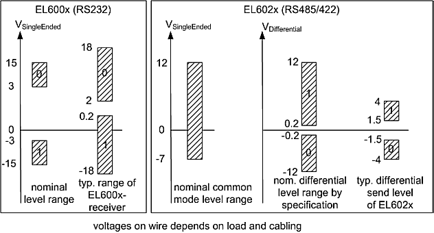 Fig.4: Level interfaces RS232, RS485/422
Termination and topology
The serial RS422 and RS485 communication technologies operate with voltage levels on a 2-wire line. Reflections at high-resistance line ends can lead to signal distortion. For this reason termination resistors are required at the receiver. For RS422/485 these are 120 Ω resistors, which together with the line resistance result in a voltage drop over the transmission link.
 | Permitted cable length The line resistance together with the termination resistor results in an overall voltage drop over the transmission link. An unacceptably high number of termination resistors would result in excessive attenuation of the signal. The system design should ensure that the voltage does not drop below 200 mV at the receiver (see Fig. ), which is the minimum voltage required. |
In RS422 mode each line must be terminated with 120 Ω at the receiver.
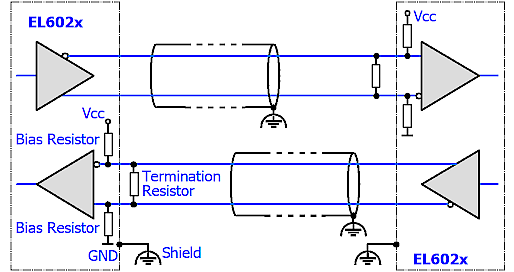 Fig.5: RS422 termination
In RS485 mode with several devices, termination resistors are only used at the two end devices.
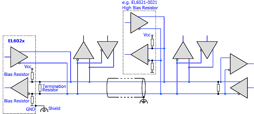 Fig.6: RS485 termination
The background is the different design of RS422/EIA-422 and RS485/EIA-485:
- RS422: 1 Tx → Rx n (maximum 10 receivers)
- RS485: n Tx → Rx m (maximum 32/128 devices, depending on the resulting bus loading)
Components for RS485 usually have a higher input impedance, resulting in lower bus load.
| Termination with EL602x and BIAS resistors The EL602x devices do not have integrated termination resistors, in order to enable operation in bus mode. Any termination that may be required must be connected outside the terminal. |
Topology
The termination and the bias resistors generate a load on the bus. However, they are essential for unambiguous bus levels and therefore have to be positioned with diligence. Ideally the RS422/485 bus should be configured as a daisy chain or a simple chain, see Fig. The following topologies may be problematic:
- Star topologies: each end point should ideally be terminated, but this can lead to excessive bus loading and ambiguous signal levels. Other potential issues are reflections and runtime variations.
- Intermeshed topologies: no clear end points, which means reflections and circulating currents are possible.
Shielding/shield
Notice | |
Do not use functional earth for discharge of residual currents or potential differences! The EL60xx units offer a shielded connection for discharging EMC interference via the cable shield (FE, functional earth). The shield must not be misused for discharging residual currents or potential differences. |