Micro-increments
The "micro-increments" function offers the option to interpolate additional increments between the counted encoder increments and thus increase the resolution of the counter value.
Functional principle of micro-increments
The following figure illustrates the functional principle of micro-increments. It is based on the interpolation of increments (orange) within real measured encoder increments (blue). To simplify the display, only four micro-increments are shown between the encoder increments. The current velocity is measured based on the internal period value measurement, and the micro-increments are interpolated accordingly. The interpolation resolution is 8 bits, which corresponds to 256 values. The counter value with micro-increments comes close to the real axis position. This is particularly useful at slow velocities, since an encoder with low resolution becomes a high-resolution axis encoder when micro-increments are enabled.
Example:
- Encoder with 1,024 lines
- 4-fold evaluation
- Micro-increments enabled, 8 bits
1024 lines * 4-fold evaluation * 256 micro-increments = 1,048,567 lines
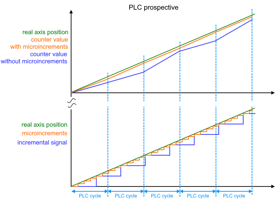 Fig.172: Functional principle of micro-increments
 | DC mode for micro-increments In order to be able to use the micro-increments function in a meaningful way, the terminal should be operated in "DC synchron" or "DC synchron (input based)" mode. Due to the distributed clocks technology the counter value is determined in a cyclically constant manner. |
Micro-increments sequence
- Micro-increments are enabled via index 0x80n0:0A "Enable micro increments"
- The micro-increments are represented in the last 8 bits of index 0x60n0:11 "Counter value".
- The period value of the input signal should be greater than 1.34 µs, so that the micro-increments can still be calculated. If this is not the case, the overrun is indicated by index 0x60n0:08 "Extrapolation stall" in the process data.
- If the "Extrapolation stall" bit is TRUE, the 8 bits of the micro-increments in the "Counter value" are set to zero.