EL5102 - Connection
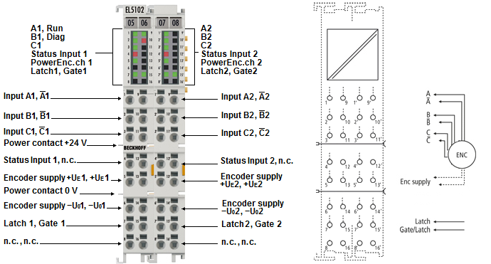 Fig.27: EL5102 - Connection
Connection left side (encoder 1) | ||
|---|---|---|
Terminal point | No. | Comment |
A1 | 1 | Encoder input A1 |
B1 | 2 | Encoder input B1 |
C1 | 3 | Encoder input C1 |
Status input 1 | 4 | Status input 1 |
+Ue1 | 5 | Encoder supply (5 V default, parameterizable 12 V, 24 V) |
-Uo1 | 6 | 0 V encoder supply |
Latch 1 | 7 | Latch extern input |
n.c. | 8 | not connected |
A̅1 | 9 | Encoder input A̅1 |
B̅1 | 10 | Encoder input B̅1 |
C̅1 | 11 | Encoder input C̅1 |
n.c. | 12 | Do not connect the terminal point |
+Ue1 | 13 | Encoder supply (5 V default, parameterizable 12 V, 24 V) |
-Uo1 | 14 | 0 V encoder supply |
Gate 1 | 15 | Gate 1 input, can be used as gate input and as Latch extern 2 input for encoder 1. This input is also referred to as Gate/Latch 1 input. |
n.c. | 16 | not connected |
Pin assignment right side (encoder 2) | ||
|---|---|---|
Terminal point | No. | Comment |
A2 | 1' | Encoder input A2 |
B2 | 2' | Encoder input B2 |
C2 | 3' | Encoder input C2 |
Status input 2 | 4' | Status input 2 |
+Ue2 | 5' | Encoder supply (5 V default, parameterizable 12 V, 24 V) |
-Uo2 | 6' | 0 V encoder supply |
Latch 2 | 7' | Latch extern input |
n.c. | 8' | not connected |
A̅2 | 9' | Encoder input A̅2 |
B̅2 | 10' | Encoder input B̅2 |
C̅2 | 11' | Encoder input C̅2 |
n.c. | 12' | Do not connect the terminal point |
+Ue2 | 13' | Encoder supply (5 V default, parameterizable 12 V, 24 V) |
-Uo2 | 14' | 0 V encoder supply |
Gate 2 | 15' | Gate 2 input, can be used as gate input and as Latch extern 2 input for encoder 2. This input is also referred to as Gate/Latch 2 input. |
n.c. | 16' | not connected |
Notice | |
Setting the encoder supply voltage
|