LEDs and connection
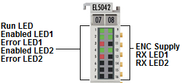 Fig.25: EL5042 - LEDs
Notice | |
Possible damage of devices: Note encoder supply voltage! Note the limit values for the supply voltage specified in the data sheets of the encoder manufacturers. The encoder supply voltage may have to be adjusted in object 0x80p8:12 (5 V or 9 V)! |
LEDs
LED | Color | Meaning | |
|---|---|---|---|
RUN (1) | green | This LED indicates the terminal's operating state: | |
off | State of the EtherCAT State Machine: INIT = initialization of the terminal | ||
flashing | State of the EtherCAT State Machine: PREOP = function for mailbox communication and different standard-settings set | ||
single flash | State of the EtherCAT State Machine: SAFEOP = verification of the sync manager channels and the distributed clocks. Outputs remain in safe state | ||
on | State of the EtherCAT State Machine: OP = normal operating state; mailbox and process data communication is possible | ||
flickering | State of the EtherCAT State Machine: BOOTSTRAP = function for terminal firmware updates | ||
ENABLED 1 (2) | green | ON | Connected encoder for the corresponding channel initialized and ready for operation (Ready bit is set) |
OFF | Connected encoder for the corresponding channel not ready for operation (Ready bit is not set) | ||
ERROR 1 (3) | red | ON | No encoder connected to the corresponding channel, or position values invalid (TxPDO bit set) |
OFF | No error | ||
ENC SUPPLY (9) | green | ON | Encoder voltage present |
OFF | 24 V field voltage missing or encoder voltage overload | ||
RX 1 (10) | green | FLASHES | Terminal receives position values at the corresponding channel |
Connection
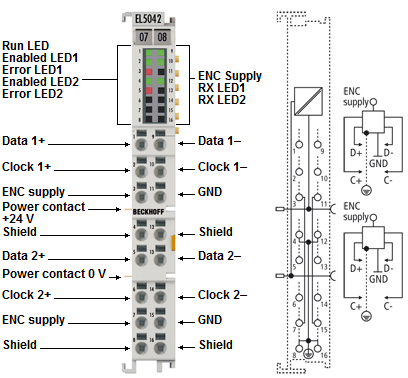 Fig.4: EL5042 - Connection
Notice | |
Encoder supply via the terminal The encoder supply voltage (5 V or 9 V), which can be set in object 0x80p8:12, can be taken from the terminal points 3 (channel 1) and 7 (channel 2). |
Terminal point | Description | |
|---|---|---|
Name | No. | |
Data 1+ | 1 | Data + input (channel 1) |
Clock 1+ | 2 | Clock + input (channel 1) |
5 V / 9 V | 3 | Supply voltage for encoder (+5 V / +9 V) |
Shield | 4 | Shield |
Data 2+ | 5 | Data + input (channel 2) |
Clock 2+ | 6 | Clock + input (channel 2) |
5 V / 9 V | 7 | Supply voltage for encoder (+5 V / +9 V) |
Shield | 8 | Shield |
Data 1- | 9 | Data - input (channel 1) |
Clock 1- | 10 | Clock - input (channel 1) |
GND | 11 | Ground |
Shield | 12 | Shield |
Data 2- | 13 | Data - input (channel 2) |
Clock 2- | 14 | Clock - input (channel 2) |
GND | 15 | Ground |
Shield | 16 | Shield |
Data transfer medium
The BiSS-C and also SSI information (Clock and Data) are transmitted as differential signals. To ensure a good EMC immunity, also for long distances, shielded cables with twisted pair conductors should be used. The cable shield should be connected to earth at both channel ends and the two end devices should be always at the same reference potential. When using external shielded cables, particular care should be paid not to damage or to interrupt the shield itself. Shield should be connected near by the connector. Refer also to the corresponding notes of the sensor manufacturer.
The value of each termination resistor should be equal to the cable characteristic impedance, typically 120 ohms for EIA-422 or RS-422 standard.