AO Setpoint transport
The following chapters describe the operation of the PDO Value (setpoint specification for the analog output channel, Analog Output = AO).
Floating point output (Real32, default setting of the channel)
The channel expects its analog setpoint as a plain text-readable floating point value, both readable in the TwinCAT configuration
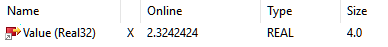 Fig.195: Value (floating point value), TwinCAT
as well as in the PLC Online View:
 Fig.196: Value (REAL) in PLC
The Real32 PDO can simply be linked to a REAL variable in PLC:
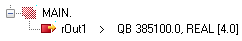 Fig.197: Linking with REAL variable
This type of transmission avoids scaling errors, as the channel itself takes into account the output range (including any range changes), commissioning and troubleshooting are considerably simplified.
Even if no unit (V, A, Ω, ..) is formally transmitted, the SI unit corresponding to the context must be used, i.e. [A] and not [mA] for a 20 mA input.
If a setpoint outside AEWtechn (output end value) is requested by the terminal, it outputs the respective maximum value and displays PDO "AO Status Overrange/Underrange + Warning":
State | Output |
|---|---|
Setpoint > AEWtechn | "Overange" + "Warning", output AEWtechn |
Setpoint < AEWtechn | "Underrange" + "Warning", output -AEWtechn |
Integer output (fixed point, INT16 or SINT16)
The channel expects its setpoint as a 16-bit fixed-point value (default incl. sign, signed integer), related to AEW (output end value):
 Fig.198: Value (fixed-point value, "INT)"
The value range extends over -32767 ...0 ... 32768, knowledge of the output range is required for interpretation and transformation on the control side, e.g. 10V ~ x7FFF = 32767 in legacy presentation
If the channel is to be linked with existing PLC code, it can be converted to this INT16 format. Otherwise, the default setting "Real32" is recommended.
As no oversized values can be specified in INT16 format, no warning is evaluated.