Data flow AO (Analog Output)
The signal acquisition and data processing of the analog output of this product is as follows:
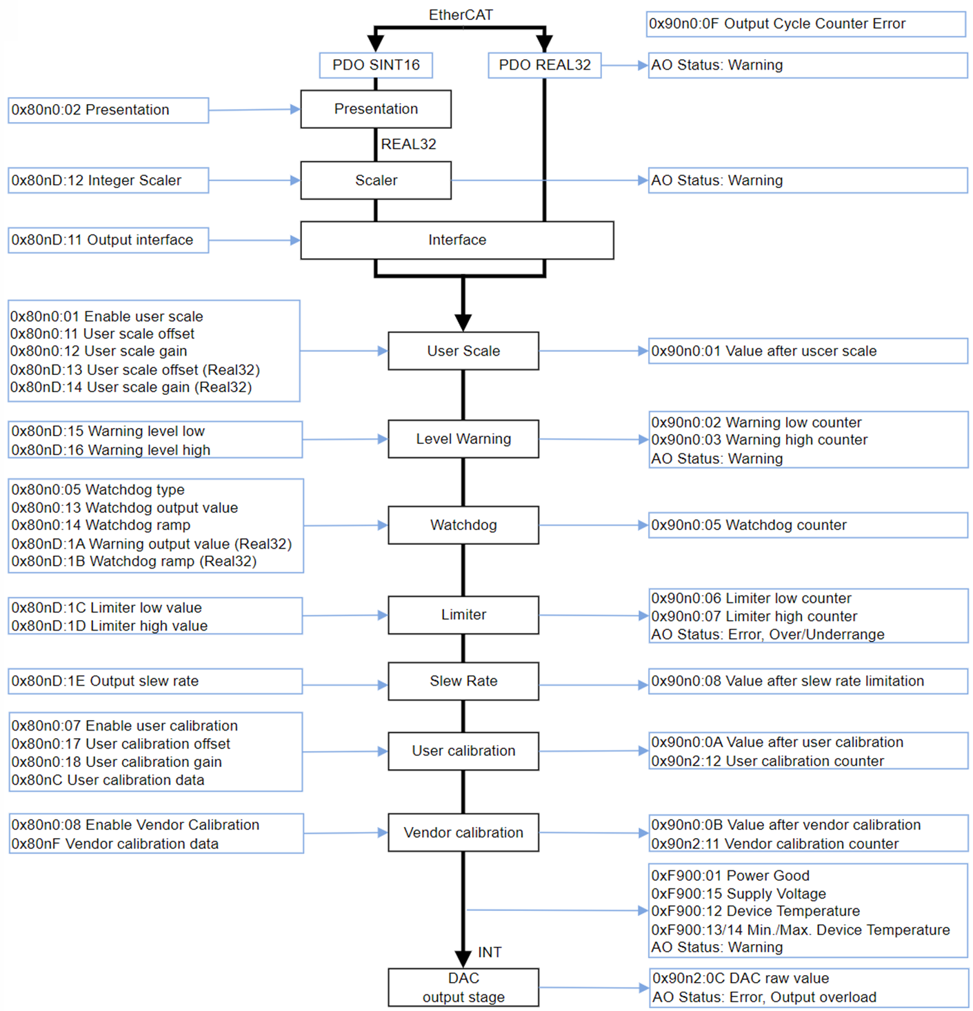 Fig.191: Data flow of the analog output
Data flow diagram legend | |
|---|---|
Left column | Changeable parameters (CoE settings or status PDO) that influence processing |
Middle column | Functional units |
Right column | Intermediate values and results, displayed in the CoE or status PDO |
This terminal calculates internally exclusively in floating point, as shown in the data flow. This considerably simplifies and shortens the commissioning of the analog channel, which minimizes errors in understanding. In addition, intermediate values along the data calculation can be easily displayed in the CoE.
The Real32 and INT16 values are defined in the CoE without units. However, the unit is determined by the context and should, wherever possible, be regarded as an SI unit. For example, the voltage is measured in volts, the current in A (even with 20 mA input!), the resistance in ohms and the ratio in V/V....
Note: Individual functional units (see data flow) have already been introduced in earlier analog devices based on INT16 (integer) and are controlled by these INT-based parameters. Such INT parameters are still supported for compatibility reasons. For example, existing code in the controller should access the CoE via ADS. This means that parameters of functional units are either
- only available as REAL32 types in the CoE if the functional unit was newly introduced with the FloatingPoint data flow, or
- are present in the CoE both as INT type and as REAL32 type with the same meaning, recognizable by the name suffix "(Real32)". The values are automatically mirrored by the firmware when they are changed or taken into account one after the other.
When re-implementing the analog function, it is recommended to use the Real32 parameters.
Commissioning of the analog output in TwinCAT should follow this data flow and is described below.