Analog input connection
Voltage measurement 0 ...10 V / -10 ... +10 V
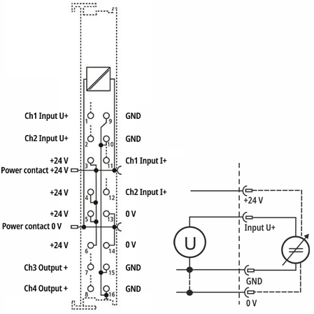 Fig.5: Connection example EL4374, voltage measurement, 2- / 4-wire
- 2-wire: 2-pin voltage measurement
- 4-wire: with 24 V supply to the sensor via the terminal
Notice | |
Short-circuiting unused inputs Unused inputs on the same device should be properly short-circuited with short cables directly at the terminal points to avoid crosstalk effects! |
Current measurement 0 / 4 … 20 mA
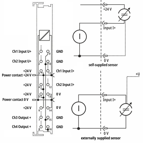 Fig.6: Connection example EL4374, current measurement, 2- / 3-wire
- 2-wire (self-supplied): Sensor is supplied via the 2-pin connection from +24 V, acts as a resistance, sensor current consumption corresponds to the sensor's own requirements, integration to 0 V available if necessary
- 3-wire (externally supplied): Sensor acts as a power source against 0 V, sensor can be externally supplied from +24 V
Notice | |
Current circuit continuously conductive regardless of CoE setting The current circuit of the channel is always continuously conductive, even if the channel is set to interface "U" in the CoE. |
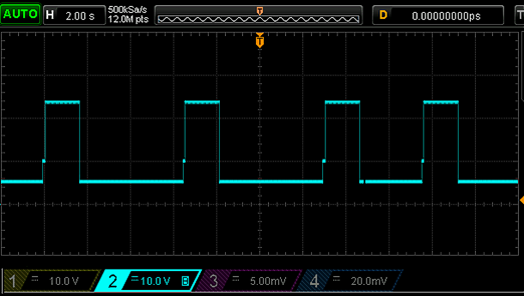 Fig.7: Example: Voltage measured via Ch1 at approx. 50 mA input current
“Auto-retry” of the current circuit at intervals of a few seconds leads to 24 V being applied briefly via the terminal input towards 0 V.
This behavior must be observed in particular if power sources are connected to the analog input "actively" (i.e. current output > 0 without a sink connected) and the source with its high open circuit voltage immediately starts to drive the current. An overload situation may occur that does not resolve itself because the current control of the source and the overcurrent protection of the input alternately block each other. To remedy this, the source must then be briefly set to 0 mA, ideally a connection under high open circuit voltage should be avoided.