Connection, display and diagnostics
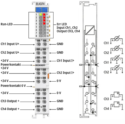 Fig.4: EL4374 LED and connection
LED | Color | Meaning | |
|---|---|---|---|
RUN | green | These LEDs indicate the terminal's operating state: | |
off | State of the EtherCAT State Machine: INIT = initialization of the terminal | ||
flashing | State of the EtherCAT State Machine: PREOP = function for mailbox communication and different default settings set | ||
single flash | State of the EtherCAT State Machine: SAFEOP = verification of the Sync Manager channels and the distributed clocks. | ||
on | State of the EtherCAT State Machine: OP = normal operating state; mailbox and process data communication is possible | ||
flickering | State of the EtherCAT State Machine: BOOTSTRAP = function for Firmware updates of the terminal | ||
ERROR | red | - Error ADC | |
ERROR | red | - Error DAC | |
Notice | |
Maximum current load of the power contacts and connection points
|
Notice | |
Cable lengths > 30 m For longer cable lengths > 30 m, suitable overvoltage protection must be provided (e.g. EL9540-0010) if corresponding interference could affect the signal cable. |
EL4374 connection
Terminal point | No. | Comment | Internally connected with connection |
|---|---|---|---|
Ch1 Input U+ | 1 | Voltage input, channel 1 | - |
Ch2 Input U+ | 2 | Voltage input, channel 2 | - |
+24 V | 3 | +24 V | 4, 5, 6; +24 V power contact |
+24 V | 4 | +24 V | 3, 5, 6; +24 V power contact |
+24 V | 5 | +24 V | 3, 4, 6; +24 V power contact |
+24 V | 6 | +24 V | 3, 4, 5; +24 V power contact |
Ch3 Output U+ | 7 | Voltage/current output, channel 3 | - |
Ch4 Output U+ | 8 | Voltage/current output, channel 4 | - |
GND | 9 | Analog ground (reference potential for Ch1...Ch4) | 10, 15, 16 |
GND | 10 | Analog ground (reference potential for Ch1...Ch4) | 9, 15, 16 |
Ch1 Input I+ | 11 | Current input, channel 1 | - |
Ch2 Input I+ | 12 | Current input, channel 2 | - |
0 V | 13 | 0 V | 14; 0 V power contact |
0 V | 14 | 0 V | 13; 0 V power contact |
GND | 15 | Analog ground (reference potential for Ch1...Ch4) | 9, 10, 16 |
GND | 16 | Analog ground (reference potential for Ch1...Ch4) | 9, 10, 15 |