Device diagnostic functions
The following EL407x device information can be read from the CoE:
Index | Name | Meaning |
|---|---|---|
0xF900:01 | Power Good | FALSE: There is approx. < 20.4 V at the power contacts. Operation of the device below this limit is not recommended. |
0xF900:11 | Operating Time | operating time of the device in [min], cannot be deleted |
0xF900:12 | Device Temperature | current internal terminal temperature in [°C]. |
0xF900:13 | Min. Device Temperature | minimum value ever observed by the terminal in [°C], cannot be deleted |
0xF900:14 | Max. Device Temperature | maximum value ever observed by the terminal in [°C], cannot be deleted |
The status of the 5 terminal LEDs can be read electronically as follows:
Index | Name | Meaning |
|---|---|---|
0xF915:01 | RUN | RUN-LED |
0xF915:09 | Error Ch.1 | LED channel 1 (AI) |
0xF915:0A | Error Ch.2 | LED channel 2 (AI) |
0xF915:0B | Error Ch.3 | LED channel 3 (AO) (if present) |
0xF915:0C | Error Ch.4 | LED channel 4 (AO) (if present) |
0xF915:0D | Error Ch.5 | LED channel 5 (AO) (if present) |
0xF915:0E | Error Ch.6 | LED channel 6 (AO) (if present) |
0xF915:0F | Error Ch.7 | LED channel 7 (AO) (if present) |
0xF915:10 | Error Ch.8 | LED channel 8 (AO) (if present) |
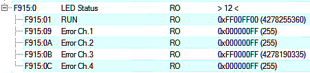 Fig.150: Subindices Index F915, example values EL4074
The status of the optical displays (LEDs) in the device can be read out electronically in CoE 0xF915 LED Status, e.g. for simultaneous LED display in the visualization.
These are four bytes that describe the RGB value and the light status:
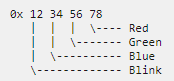
- Byte 1 (from left to right): Flashing/lighting code
- 0x00: Off/ not available
- 0x01…0x14: 1..20 Hz
- 0x80: EtherCAT PreOp
- 0x81: EtherCAT SafeOp
- 0x82: EtherCAT Boot
- 0xFF: On/ available
- Byte 2..4:
- 0x00: Off
- 0xFF: On
Examples:
- 0x 00 00 00 00: LED not present
- 0x FF 00 00 00 : LED is on, RGB =0, i.e. not illuminated, meaning: LED is present
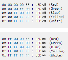 Fig.151: Examples LED status