Instructions for use
Parallel connection in current mode
The current outputs of the EL407x are single-ended and can be connected in parallel to add their currents to the load. Ohm's law must be observed, the internally available output voltage does not increase!
Examples
- EL4072, max. 750 ohm load see technical data -> 15 V output voltage is available internally
-> if 100% output (20 mA each) is required for all channels and thus ∑= 40 mA, the load must be < 375 ohm. - EL4074, max. 500 ohm load see technical data -> 10 V output voltage is available internally
-> if 100% output (20 mA each) is required for all channels and thus ∑= 80 mA, the load must be < 125 ohm. - EL4078, max. 300 ohm load see technical data -> 6 V output voltage is available internally
-> if 100% output (20 mA each) is required for all channels and thus ∑= 160 mA, the load must be < 37 ohm.
Output behavior, rise time
You can expect approx. 3 ms for 0->90% and approx. 6 ms for 0->100%
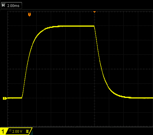 Fig.153: Rise time representation
Output behavior, dynamics
The output behavior is designed for a dynamic range of 2 ksps/500 µs (setpoint specification). This means that low dynamic signals are output. The output terminals of the EL41xx series are recommended for the output of frequencies above 200 Hz.
Spontaneous output when switching on/off ("glitch")
When the Us supply (E-bus) is switched on or spontaneously switched off and on again, there may be brief, independent value output in the range of a few ±10% of the FSV for a few ms.
When the Up supply (power contacts) is switched on or spontaneously switched off and on again, there may be brief, independent value output in the range of a few ±% of the FSV for a few ms.
It is recommended that sensitive signal receivers only be switched to receive mode when the terminal/channel
- is in the OP state
- does not report a warning or error in the PDO state
If a glitch-free output is required, output terminals from the EL417x series can be used.