EL4074
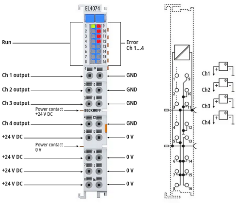 Fig.8: EL4074 LED and connection
LED | Color | Meaning | |
|---|---|---|---|
RUN | green | These LEDs indicate the terminal's operating state: | |
off | State of the EtherCAT State Machine: INIT = initialization of the terminal | ||
flashing | State of the EtherCAT State Machine: PREOP = function for mailbox communication and different default settings set | ||
Single flash | State of the EtherCAT State Machine: SAFEOP = verification of the Sync Manager channels and the distributed clocks. | ||
on | State of the EtherCAT State Machine: OP = normal operating state; mailbox and process data communication is possible | ||
flickering | State of the EtherCAT State Machine: BOOTSTRAP = function for Firmware updates of the terminal | ||
ERROR | red | - Analog output overload: | |
Notice | |
Cable lengths > 30 m For longer cable lengths > 30 m, suitable overvoltage protection must be provided (e.g. EL9540-0010) if corresponding interference could affect the signal cable. |
EL4074 connection
Terminal point | No. | Description | Internally connected with connection | Max. current carrying capacity *) |
|---|---|---|---|---|
Ch1 output | 1 | Voltage/current output, channel 1 | - | overload protected |
Ch2 output | 2 | Voltage/current output, channel 2 | - | overload protected |
Ch3 output | 2 | Voltage/current output, channel 3 | - | overload protected |
Ch4 output | 2 | Voltage/current output, channel 4 | - | overload protected |
+24 V DC | 5 | +24 V | 6; 7, 8 +24 V power contact | 1 A |
+24 V DC | 6 | +24 V | 5, 7, 8 +24 V power contact | 1 A |
+24 V DC | 7 | +24 V | 5, 6, 8 +24 V power contact | 1 A |
+24 V DC | 8 | +24 V | 5, 6, 7, +24 V power contact | 1 A |
GND | 9 | Analog ground (reference potential for Ch1...Ch4) | 10, 11, 12 | 100 mA **) |
GND | 10 | Analog ground (reference potential for Ch1...Ch4) | 9, 11, 12 | 100 mA **) |
GND | 11 | Analog ground (reference potential for Ch1...Ch4) | 9, 10, 12 | 100 mA **) |
GND | 12 | Analog ground (reference potential for Ch1...Ch4) | 9, 10, 11 | 100 mA **) |
0 V | 13 | 0 V | 14, 15, 16, 0 V power contact | 1 A |
0 V | 14 | 0 V | 13, 15, 16, 0 V power contact | 1 A |
0 V | 15 | 0 V | 13, 14, 16, 0 V power contact | 1 A |
0 V | 16 | 0 V | 13, 14, 15, 0 V power contact | 1 A |
*) Constant current; short-term higher currents are to be avoided and can cause thermal overload (damage)
**) The "GND" potential is internally coupled to the "0V" potential, but is subject to a reduced current carrying capacity
Voltage output 0...10 V / -10...+10 V
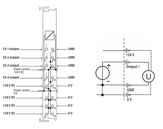 Fig.9: Connection example EL4074, voltage output, 2-/4-wire
- 2-wire: 2-pin voltage output; 4-wire: with additional 24 V power supply to the actuator
Current output -20 / 0 / +4…+20 mA
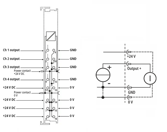 Fig.10: Connection example EL4074, current output, 2-/4-wire
- 2-wire: 2-pin current output; 4-wire: with additional 24 V power supply to the actuator