Watchdog
This output channel is equipped with a safety device (watchdog). This moves the output to a predefined setpoint if process data traffic to the output device is interrupted.
Setting the watchdog time
The watchdog time, i.e. the time at which the watchdog case is triggered, is set via the general TwinCAT dialog "Advanced Settings" -> General -> Behavior -> Watchdog -> "Set Multiplier" and "SM Watchdog" (SM = SyncManager).
 | Notes on settings
|
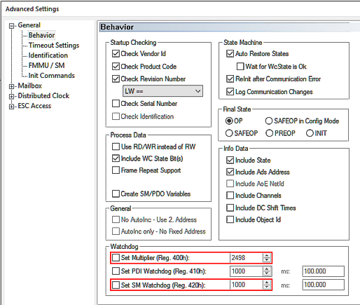 Fig.175: Watchdog settings, here: 100 ms
Watchdog time [ms] = Multiplier * SM Watchdog [ms]
A maximum watchdog time of 65 s is possible. Larger values are calculated modulo 65, for example 70 s would be shortened to 5 s.
Notice | ||
 | General notes on watchdog settings Observe the general notes on the watchdog settings. | |
Sequence of the watchdog case
The sequence is as follows:
- As long as the channel is properly and regularly supplied with EtherCAT process data, they are output. The watchdog observes this without further action; they say "it is being brought up".
- As soon as the data no longer arrives (e.g. due to a wire break, EtherCAT master stopped, etc.), the output value remains at the last value. The watchdog now starts to run down. If data arrive again in time, the watchdog returns to the start value.
The EtherCAT device remains in the OP state, even if it cannot be reached from the master. - If the watchdog has expired, i.e. the time set as above has elapsed without new data arriving, the set substitute value is output.
The EtherCAT devices returns to the Safe-OP state (recognizable by the slow flashing of the EtherCAT RUN-LED if present). - As soon as new data arrives and the EtherCAT SubDevice has been reset to OP mode by the master (TwinCAT), it is output again and the watchdog resumes monitoring.
- The watchdog value is also output permanently and immediately (without waiting time) if the device leaves the OP state for other reasons.
Setting the watchdog behavior
The following settings can be made for the watchdog, starting from index 0x80n0:05 "Watchdog Type":
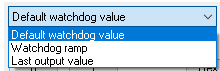 Fig.176: Selection "Watchdog Type"
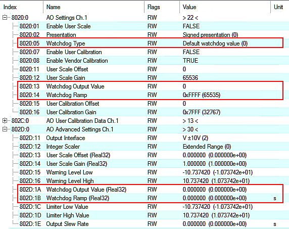 Fig.177: Indices for watchdog settings
Values Index 0x80nD, | Meaning |
|---|---|
Default watchdog value (default) | The analog output value is set without transition to the user-specific substitute value/setpoint according to index 0x80n0:13 or index 0x80nD:1A (default: 0) |
Watchdog Ramp | Likewise, substitute value/setpoint according to index 0x80n0:13 or index 0x80nD:1B, but linear ramp to that point. The gradient of the ramp must be specified in relation to AEWnom
If, for example, a gradient of 2 V/sec is required with AEWnom = 10 V, the "Watchdog Ramp (Real32)" = 5 [sec] or (with "Extended Range" -> 327 µV/digit) "Watchdog Ramp" = 6 [digit/ms]. Default value: 0 (no ramp) |
Last Output value | Last output value remains |
Examples
An EL4078 outputs a staircase signal, watchdog time set to 1 second, substitute value 7 V. Demonstration of various events:

Watchdog Counter
Each watchdog event is counted in index 0x90n0:05 “Watchdog Counter” (secured against power failure).
Notice | |
Note on resetting the watchdog counters As the watchdog is a device property, it is displayed for each output channel but has the same value for all channels. When a watchdog counter is reset, all other channel-specific watchdog counters are also reset. |
The counter is reset
- by the command x403n to index 0xFB00:01 (channel 1: n = 0, channel 2: n = 1, ...), the success is displayed with "255" in index 0xFB00:03 "Response".
- and by command x4001 "Reset all AO Counter"
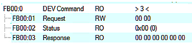 Fig.173: CoE Index 0xFB00, „DEV Command“
During command execution, "Status" 255 "busy" is displayed in index 0xFB00:02, "0" means "successfully completed"
The firmware responds to an unknown command with
 Fig.174: General parameter incompatibility reason, 0x06040043