EL37x2 - Pin assignment
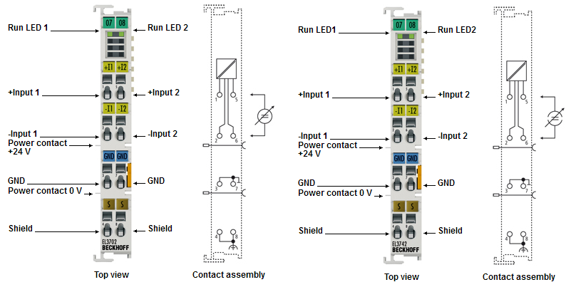
Pin assignment and wiring
|
Terminal point |
Description | |
|---|---|---|
|
Name |
No. | |
|
+ Input 1 |
1 |
+ Input 1 |
|
- Input 1 |
2 |
- Input 1 |
|
GND |
3 |
Signal ground for input 1 (internally connected to terminal point 7) |
|
Shield |
4 |
Shield |
|
+ Input 2 |
5 |
+ Input 2 |
|
- Input 2 |
6 |
- Input 2 |
|
GND |
7 |
Signal ground for input 2 (internally connected to terminal point 3) |
|
Shield |
8 |
Shield |
Electrical isolation of the inputs
Sample: EL3602 wiring
In figure 2, the circuit diagram with a variable voltage source (channel 2) should be regarded as equivalent to the configuration of channel 1 with a sensor and measuring amplifier.
Sample: EL3742 wiring
In figure 2, the circuit diagram with a variable current source (channel 2) should be regarded as equivalent to the configuration of channel 1 with a sensor.